Amplifiers, solid state discrete, tubes or chip amps,
they all can need some evaluating and testing.
Small circuits, transistor- or op-amp based can be built to supply some different test signals.
I bet some of you have some good basic transistor circuits to share here.
I start by pointing to a website with a few useful op-amp circuits
for generating high quality sine, square and triangle wave.
Using Op-Amps it is not very difficult generating test signals of different shapes.
I say anyone that can buy a few op-amps can do this.
Most useful is of course sine waves as they comes closer to the nature of analog sound
than the other, triangle & square waves.
Other waveforms very useful for testing if you have oscilloscope are sawtooth waves.
There are 2 kinds of them: Rising and Falling sawtooth
http://en.wikipedia.org/wiki/Sawtooth_wave
At this site I found some basic sine, square- and triangle wave generator circuits schematics.
Shown is basic information how to create these test waves:
http://www.play-hookey.com/analog/sine_wave_generator.html
This is a schematic of a sine wave generator.
With both sine and cosine waves available,
this circuit is sometimes known as a quadrature oscillator.
😉 lineup audio lab 😉
>> lineup.awardspace.com <<
they all can need some evaluating and testing.
Small circuits, transistor- or op-amp based can be built to supply some different test signals.
I bet some of you have some good basic transistor circuits to share here.
I start by pointing to a website with a few useful op-amp circuits
for generating high quality sine, square and triangle wave.
Using Op-Amps it is not very difficult generating test signals of different shapes.
I say anyone that can buy a few op-amps can do this.
Most useful is of course sine waves as they comes closer to the nature of analog sound
than the other, triangle & square waves.
Other waveforms very useful for testing if you have oscilloscope are sawtooth waves.
There are 2 kinds of them: Rising and Falling sawtooth
http://en.wikipedia.org/wiki/Sawtooth_wave
At this site I found some basic sine, square- and triangle wave generator circuits schematics.
Shown is basic information how to create these test waves:
http://www.play-hookey.com/analog/sine_wave_generator.html
An externally hosted image should be here but it was not working when we last tested it.
This is a schematic of a sine wave generator.
With both sine and cosine waves available,
this circuit is sometimes known as a quadrature oscillator.
😉 lineup audio lab 😉
>> lineup.awardspace.com <<
ummm... The site must be offline or something, I'm not getting the picture or the site when I click on the link. I know of a site with some generators. Though I don't know of their quality, but I believe it would depend more on the OPamps and components used.
http://www.4qdtec.com/#indx
PS: Any ideas of the usefulness of the circuits on this site?
http://www.4qdtec.com/#indx
PS: Any ideas of the usefulness of the circuits on this site?
IMO, simple oscillators are fun to build and test, but when it comes to running tests on amp circuits it is better to just fork it out for a decent function generator.🙂 So much easier and more precise.
CBS240 said:IMO, simple oscillators are fun to build and test, but when it comes to running tests on amp circuits it is better to just fork it out for a decent function generator.🙂 So much easier and more precise.
thanks CBS240
yeah,
I can think of at least 3 ways to create test signals
1. build a circuit - the DIY way
2. use a generator machine you buy ( this is my own way )
3. use your CD-player, with a recording of different signals
Number 3 using CD
will give VERY high quality signals!
I have one such Test-Signal record, originally designed for CarAudio testing purpose.
Nevertheless, it can be fun and you will learn something useful
by building your own sine wave circuit.
Most simple is using only 2 transistors followed by a RC-filter at the output
to make such a test-signal!
😎 >> lineup Audio Lab << 😎
dunno if they are still around, but eXar used to make a chip that did all three functions, sine, triangle and square in a single chip.
if you want low distortion sine waves, you need a "fancy" circuit. 😉
or, as someone mentioned, a CD recording, or the output of your computers sound card...
_-_-bear
if you want low distortion sine waves, you need a "fancy" circuit. 😉
or, as someone mentioned, a CD recording, or the output of your computers sound card...
_-_-bear
I have my computer connected to my sound system, but I haven't gotten around testing it with my scope. I suppose a 10Mohm impedance on the speaker outputs won't hurt anything, right? Or do I need an impedance matching circuit to get real-life data? If so, can someone post a simple matching circuit?
I don't want this to become a full-blown threadjack, just so y'all know.
EDIT: would 4.7 ohm and 3.3 ohm resistors in series with the scope connected in their centerpoint and ground work?
I don't want this to become a full-blown threadjack, just so y'all know.
EDIT: would 4.7 ohm and 3.3 ohm resistors in series with the scope connected in their centerpoint and ground work?
Keantoken,
It is certainly better to have a dummy load, and the simplest one is an 8 ohm resistor (necessary wattage of course; but it does not necessarily need to be non-inductive, as loudspeakers become inductive at high frequencies anyway).
I have a test load circuit equivalent to my loudspeakers, but is is quite involved, and speakers can differ quite substantially. I would suggest both open circuit and loaded output tests, though some commercial amplifiers do not like open circuit. Hopefully they will tolerate at least 80 ohms for an 8 ohm system. Good square wave response at both will ensure that your amplifier is probably without blame for most loudspeaker loads.
Though I have a commercial signal generator, I would agree with the fun factor of building one - have done that too! Only if one goes to spectrum (distortion) analysis a very low distortion sine wave generator is necessary, unless of course one has access to a modern complete spectrum analyser. Such a sine wave generator can also be home built for at least 2 frequencies. (Suitable state-variable circuits capable of about 0,002% distortion is shown in a rather old book by Walter Jung on op-amps. Unfortunately I am unable to give the title now as I am not at home.)
Regards.
Just so everybody knows, the amp that I use is the one on top of my TV in my avatar. Either it is a good amp, I am just a bad listener, or my speakers just cancel out the distortion. 
The only inductor I have is 100uH. Is there any way that I can turn this into a suitable speaker model? I all sorts of capacitors but I can't find any source of inductors that I can use. All I can think of for speaker models would be 4.3 and 3.3 ohm resistors in series.
The only inductor I have is 100uH. Is there any way that I can turn this into a suitable speaker model? I all sorts of capacitors but I can't find any source of inductors that I can use. All I can think of for speaker models would be 4.3 and 3.3 ohm resistors in series.
Hi lineup,
The most important part of the story : a pc base simulated oscilloscope. Is there any place we can get information about this or download this software? I guess we have to make a small circuit before we can do this, any info. on this ?
Tks.
The most important part of the story : a pc base simulated oscilloscope. Is there any place we can get information about this or download this software? I guess we have to make a small circuit before we can do this, any info. on this ?
Tks.
I don't know anything if your looking for a PC scope, but there is a program called audacity that can generate sine and square waves and can be used to view the recorded waveforms. It is here:
http://audacity.sourceforge.net/
It has barely any problems and is completely free! Enjoy...
http://audacity.sourceforge.net/
It has barely any problems and is completely free! Enjoy...
Hi Kean,
the 4r7 and 3r3 will not dissipate the same power when operating in series. The 4r7 will dissipate about 42% more power than the 3r3. Take that into account when designing the heatsinks for the resistors.
I think the test resistor needs to be substantially non inductive for the frequencies that are used as test signals.
The highest frequency you are likely to use is 10kHz. At this frequency even a wire wound will be substantially non inductive. Do not forget that operating an amplifier into a reactive load SERIOUSLY stresses the output and driver stage many times worse than driving a purely resistive load.
If you want an amp that is capable of driving an 8ohm reactive load (a speaker) then I recommend testing at 4r as well as at 8r.
If you plan on using either 6ohm or 4ohm speakers then your test loads need to be scaled accordingly.
You can't generate squarewaves with a pc based signal generator, the bandwidth of a squarewave is way too high.
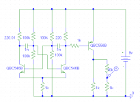
But, there is a simple way out, i use the attached circuit as squarewave generator. It's not perfect, but way good enough to test an amplifier. Frequency is ~10khz.
Another possibility would be connecting a schmitt-trigger to the soundcards output, this way you can create squarewaves with variable frequency.
Mike
Attachments
Pick up Jim Williams excellent book "Analog Circuit Design" -- he sketches several low distortion oscillator ideas.
I don't know how much oomph you can get out of an IC based oscillator -- Ron Mancini (one of the design guys at TI who writes a column for EDN) states that voltage feedback opamp based oscillators run out of bandwidth.
the easiest low distortion oscillator which I have used was based upon a CMOS clock generator and a couple of switched capacitor filters -- the ideas is to knock down the 2nd and higher harmonics -- the idea was in AudioXpress (I think Charles Hansen was the author) but I had earlier implemented it with a BasicStamp micro-controller.
"Analog Circuit Design" should be on everyone's bookshelf, along with "OpAmp Applications Handbook" by Walt Jung and "Trouble Shooting Analog Circuits" by Bob Pease...and to think that my wife complains that I read this stuff while she watches "Jane Eyre" on TV.
the best oscillator I ever built -- there's a thread on this somewhere -- the current feedback design from Linear Technology -- ain't no distortion in this one but it is tricky keeping it going. -- and it operates at 10kHz -- this is a pic of the residuals:
An externally hosted image should be here but it was not working when we last tested it.
As I recall, the first product from HP was the 200 oscillator which used the nonlinear characteristics of a light bulb for stability. Linear Technology published an excellent article on low distortion sine wave generators based on this principle using opamps. It was in a an app notes book in the late 80's.
I use a USB oscilloscope from USB instruments for non critical work at my day job. Below is the link. The main reason I use it is to be able to display signals in real time during presentations for UPS systems. for this application I have to use isolation probes. The scope also has a function generator built in.
DS1M12 sope
I bought my scope from Saelig instruments. They have a lot of cool stuff.
Saelig Instruments
d3imlay said:Linear Technology published an excellent article on low distortion sine wave generators based on this principle using opamps. It was in a an app notes book in the late 80's.
The oscillator shown in the pic is the Linear Tech design using current feedback amplifiers -- the ones you describe are all codified in Jim Williams excellent book "Analog Circuit Design" --
bear said:dunno if they are still around, but eXar used to make a chip that did all three functions, sine, triangle and square in a single chip.
if you want low distortion sine waves, you need a "fancy" circuit. 😉
or, as someone mentioned, a CD recording, or the output of your computers sound card...
_-_-bear
XR8038 or MAX038
http://www.maxim-ic.com/quick_view2.cfm/qv_pk/1257
Jan Didden
jackinnj said:
MAX038 is "past tense"
Really? I have a design out there that is still being produced that used it. Paramedical stuff, generating 'curative' waveforms 😉 .
For a new design, yes, I would probably mate a PIC with a DDS chip.
Jan Didden
- Status
- Not open for further replies.
- Home
- Amplifiers
- Solid State
- Sine wave - Square & Triangle wave generator using Transistors / OP-Amps