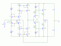
First: 100 ohms input impedance? A bit low, don't you think?
Second: As amp it will work but you must consider different transistors (not 100% alike) and establish working conditions.
Your design is pretty much alike mine and it works splendidly. As pointed out earlier, the power supply must be clean due to poor PSRR.
You must have 22-47 pF at least from the Q11, Q12 collectors down to ground in order to get a nice step response.
There is a difference in behaviour of non-inverting and inverting circuit of this kind. For gain like 10x it does not matter, for 1x the inverting behaves much better. We could increase input impedance of the inverting to some 1k and FB to 10k and still having excellent parameters. Buffer at the input would be needed. Not a case for non-inverting.
What kind of comments? This is a "PIM-free" topology
What kind of comments? This is a "PIM-free" topology
Very good parameters. I have tried in practice, but with input buffer the same as QRV08. Look at post: http://www.diyaudio.com/forums/showthread.php?postid=784679#post784679
Sorry, Per Anders I have a debt photo.
Sorry, Per Anders I have a debt photo.
Agreed, VFB is more usual "textbook" kind of solution.
It is interesting that VFB was so widely used for fast AC signals, though its strongest point is DC accuracy, which is not necessarily needed for audio.
CFB's strongest point is fast AC signals transfer, why was it overlooked?
It is interesting that VFB was so widely used for fast AC signals, though its strongest point is DC accuracy, which is not necessarily needed for audio.
CFB's strongest point is fast AC signals transfer, why was it overlooked?
Sorry for the second question, I'm answered myself. 
For
I1 = Ic1 + Ib1 + Ib4
I2 = Ic2 + Ib2 + Ib3
I3 = Ib15 + Ie13
I4 = Ib16 + Ie14
At the condition of the same transistor , we can reduce :
I1 = Ic + 2 × Ib
I2 = Ic + 2 × Ib
Correct me if i'm wrong, i am a beginner in electronic.
Have a nice day.
For
I1 = Ic1 + Ib1 + Ib4
I2 = Ic2 + Ib2 + Ib3
I3 = Ib15 + Ie13
I4 = Ib16 + Ie14
At the condition of the same transistor , we can reduce :
I1 = Ic + 2 × Ib
I2 = Ic + 2 × Ib
Correct me if i'm wrong, i am a beginner in electronic.

Have a nice day.
MaxS said:Nice job !
Yesterday, I started a simulation of your preamp but i've put all the same transistors and i think my problem goes from here else could you give us the value of DC source.
Thanks you a lot
I would try something like 2mA for I1/I2 and 5mA for I3/I4 with +/-15V supply. Use some 1A output transistors with Ic ~15mA.
For input stage, I1 = I2 = 5mA. Can be reduced to 1mA, with some loose of speed.
For diamond buffer, I3=I4=1mA.
Use fast, low capacitance transistors at input stage.
Distortion = 0.0002% for 2Vp-p, 0.002% for 20Vp-p, low order harmonics. Almost no slew rate limitation, no danger of phase modulations.
For diamond buffer, I3=I4=1mA.
Use fast, low capacitance transistors at input stage.
Distortion = 0.0002% for 2Vp-p, 0.002% for 20Vp-p, low order harmonics. Almost no slew rate limitation, no danger of phase modulations.
I don't want to reinventing the wheel so I propose to use a couple of BC 54x / 55x .
The maximal frequency are 300 MHz. Capacitances for input is 10 pF and at the output is around 1,7 and 4,5 pF. I think your two criterias are satisfied.
Not hard, I already studied your Dispre design and some other. On solid state, i always look your job. Verry happy to help you.
The maximal frequency are 300 MHz. Capacitances for input is 10 pF and at the output is around 1,7 and 4,5 pF. I think your two criterias are satisfied.
Not hard, I already studied your Dispre design and some other. On solid state, i always look your job. Verry happy to help you.
- Status
- This old topic is closed. If you want to reopen this topic, contact a moderator using the "Report Post" button.
- Home
- Amplifiers
- Solid State
- A CFB BJT preamp - any comments?

 Q1, Q2 is grounded, yes?