I did not managed to find 10,000uF (>70v) caps, the only ones they have in stock are 10,000uF (63v).
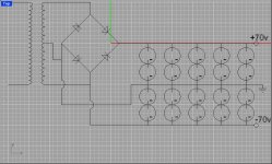
So i bought 20 4,700uF (40v)
2 capacitors in series would have a 2,350uF total capacitance
5 arrangments in parallel would give 2350 x 5 = 11,700uF
so with 20 off them i would have 11,700uF per rail
[as th arrangment shown below]
Is this going to work good? or I should add some zener diodes to the arrangment ?
Attachments
I guess anything between 22K ohms and 100K ohms will do across each capacitor . Around 0.5 watt rating is also fine. I am assuming the max V across each capacitor is 40 volts.
I just saw that 5.6K ohm suggestion. Basically I think the bleeder current through the resistor should be comparable or higher than the leakage current though the capacitor.
I just saw that 5.6K ohm suggestion. Basically I think the bleeder current through the resistor should be comparable or higher than the leakage current though the capacitor.
Drawing error?
Maybe it´s a drawing error, but you have the -70v side connected to one side of the AC line in the TRF, it should be connected to the left side of the rectifier only; the GND is connected to the rectifier, it should be connected to the center tap of the TRF only and the lower AC line should be connected to the lower side of the rectifier only.
Check this page on power supplies, it helped me a lot with mine:
http://www.zero-distortion.com/techno/powersupply/powersi.htm
Howdy Mr. leander,
Extract from the article by Dejan V. Veselinovic:
Because of their never insignificant size, bleeders are never easy to install as a later option. For them to do any reasonable work, you will need at least 2W resistors, and 5 or 10 watts is even better. The greater the power rating, the faster they can discharge the capacitors, but on the other hand, something is better than nothing.
You can work out the values yourself, remembering that current equals voltage divided by resistance, and power equals this current times the supply rail voltage. Make sure the power rating of the resistor is at least four times what you will need, because it will tend to heat up quite considerably in the period it takes to discharge the capacitors. I would prefer to see twice that; so, if you have a 2W resistor, work out its value so that current times voltage comes out as no more than 0.4-0.5 watts.
As for the discharge time, obviously the more power the resistor can soak up, the less time it will take the capacitor to discharge. But don't let this induce you to use large power resistors for the fun of it, try to strike a reasonable balance between discharge time and your desires to make it instantaneous. As an example, let's say you have a +/- 40V supply with 10,000uF/63V electrolytics of the snap-in type. If you were to use a say 6K8/2W carbon resistor, the current would be (40:6,800) 0.0059 A, or 5.9 mA. A typical snap-in capacitor of that type will provide around 4.6 amperes of current on demand, but this is when it is fully supplied with nominal voltage. Not to dig too deep into the many details one would have to dig up, do use that 6K8/2W resistor, it's quite enough.
Regards,
Elvin
Sorry, but what a messy solution. You could've gone for a bridged amp with the lower voltage and saved money and hassle.
By the way, does anyone know of a source of those DUAL PS caps the Japanese products used to use - I recall Hitachi used to make, like 15,000/15,000 in one can using 3 foils and +G- out.
Cheers,
Greg
By the way, does anyone know of a source of those DUAL PS caps the Japanese products used to use - I recall Hitachi used to make, like 15,000/15,000 in one can using 3 foils and +G- out.
Cheers,
Greg
- Status
- This old topic is closed. If you want to reopen this topic, contact a moderator using the "Report Post" button.
- Home
- Amplifiers
- Solid State
- Power supply caps