I have a simple (or simple-minded) question about the number of bridge rectifiers in a power supple. I'm building a PS with a dual secondary transformer to give one pair of +/- voltage rails. What are the advantages/disadvantages of the two options below:
1) Tie the center taps together to ground and use one bridge rectifier, like the PS designs suggested in Randy Slones' books and ESP's website.
2) Keep the center taps separate and connect each pair of secondaries to its own bridge rectifier (two). Negative rail from Bridge 1 is connected to positive rail from Bridge 2, which in turn is grounded. This approach is typically used by the Gainclone crowd and can be seen in Carlos' Snubber design.
thanks,
gar.
Have a search. This has been covered pretty extensively at least twice in the last 4 months. Starter for 10:
http://www.diyaudio.com/forums/showthread.php?s=&threadid=49327&highlight=
http://www.diyaudio.com/forums/showthread.php?s=&threadid=49327&highlight=
Using two bridges provides some common-mode EMI isolation between mains line and audio ground, but it's a poor approach
Remember that mains transformers show huge primary-secondary capacitances so all the EMI from the mains line is happily transferred to the audio circuits on the secondary side
Superior filtering and RF isolation is achieved with a common-mode filter. Use a ferrite ring core of approx. 4cm diameter made of high permeability material and wind two symmetric windings like these :
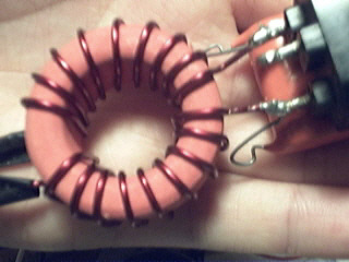
Use magnet wire of suitable gauge and do as much turns as the core can fit [the filter of the image is not fully filled because it was made in a hurry]
To further improve filtering place 470nF 630V capacitors between phase-neutral on both sides
Remember that mains transformers show huge primary-secondary capacitances so all the EMI from the mains line is happily transferred to the audio circuits on the secondary side
Superior filtering and RF isolation is achieved with a common-mode filter. Use a ferrite ring core of approx. 4cm diameter made of high permeability material and wind two symmetric windings like these :
Use magnet wire of suitable gauge and do as much turns as the core can fit [the filter of the image is not fully filled because it was made in a hurry]
To further improve filtering place 470nF 630V capacitors between phase-neutral on both sides
There is a real effect that I haven't seen mentioned here.
Assuming that there are two independent secondaries,
the dual bridge approach is sometimes preferred because:
If there is only one bridge.
If there is any net DC flow through the ground to the transformer
And there is any non-match between the secondary windings
Then the core of the transformer will tend to saturate.
As a practical example, less than 100 ma net current imbalance
on a high quality toroidal transformer is often enough to make it
buzz. I've seen LED lights on one side that could do it on a not-
so-good toroid.
EI and similarly loosely coupled transformers don't see this
effect nearly as much. (Sometimes less is more and vice versa)
This is true. Single bridge requires perfectly matched bifilar-wound secondaries in order to allow unbalanced loads between rails, otherwise dual bridges have to be used
Almost all toroids are bifilar wound, but EI tranformers aren't. However, EI transformers have higher winding resistances and have inherent air gaps due to its 'puzzle core' construction, so they cope better with volts*second imbalances
The entire problem originates when the current flow through the primary is not the same for the positive and negative halves of the mains waveform. This causes asymetric voltage drop on the mains line and the primary and thus asymetric flux is applied to the core. This also means that the effect gets worse with poor mains lines
or when the frequency of the amplifier output signal is near the double frequency of mains ...If there is only one bridge,
If there is any net DC flow through the ground to the transformer
And there is any non-match between the secondary windings
- Status
- This old topic is closed. If you want to reopen this topic, contact a moderator using the "Report Post" button.
- Home
- Amplifiers
- Solid State
- One or Two Bridge in PS?