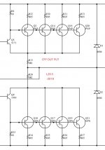
Would it make sense to use metal oxide resistors in place of the 1/4W 1% 68 Ohm metal film resistors in attached schematic?
I ask because I have a similar amplifier (the CFP version (V7) of the L20) which has 100 Ohm 1/4W 1% metal film resistors in that location. One channel blew the outputs and the one discolored resistor now measures half of the marked value.
So I was wondering if a different type of resistor and perhaps a higher power rating might prevent the resistor from decreasing in value in any future overload condition. Now I don't expect the outputs to blow again (because I am replacing the suspect quality D1047/B817 with either genuine ON (NJW0281G NJW0302G) or Toshiba (2SC5200N 2SA1943N).
However I would like to know what the best practice is.
Attachments
I generally use metal film where I can, MOX and wire-wound are only used when I need higher power but a reasonable size (3+ watts)
IMO - go back with what was there, it was working up until the failure and you should expect some damage after a failure like that.
IMO - go back with what was there, it was working up until the failure and you should expect some damage after a failure like that.
Sure, I do expect damage after a failure like that. But I would like to protect the Toshiba drivers (which are no longer made).
So I was wondering if a metal oxide and/or larger power rating would be a good idea to prevent the decrease of the 1/4W 1% metal film resistor value due to such an overload condition.
So I was wondering if a metal oxide and/or larger power rating would be a good idea to prevent the decrease of the 1/4W 1% metal film resistor value due to such an overload condition.
In fact those resistors should really be fusible (ie won't start a fire when overloaded). Anywhere where a semiconductor failing shorted puts the rail voltage across a resistor then that resistor should either be able to handle the current, blow the supply fuse, or be a fusible type so it doesn't risk starting a fire and protects the rest of the circuit. (In fact this sort of failure mode (shorting transistors) is done in commercial equipment safety tests to get a UL rating or similar).
Here the normal failure mode (transistor becomes zero ohms between all pins) would allow the emitter resistors to conduct enough current to blow the PSU fuse(s) without overheating themselves, but its not guaranteed to fail that way, and that 68 ohm could have to handle a direct short. In this instance significant current flowed in the 68 ohm resistor so its clearly a possible failure mode.
Uprating the the power handling isn't the answer, as 68 ohms across the rails would need many tens of watts to survive, which is completely untenable. You want it to fail safely if the original fault doesn't happen to blow the fuse(s).
The same logic applies to VAS emitter resistors, and around driver transistors in general.
Last edited:
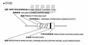
Some power amps use flame proof resistors there, so labelled at the schematic by the FP label besides value and a triangle or a "!" sign , meaning "Safety important parts, replace ONLY with same type and value"
Apparently not burning your home down is the main premise, not too worried about "sound".
Such as these:
CPF Metal Film Resistors, Axial, Industrial Power, Precision, Flameproof | Vishay
Apparently not burning your home down is the main premise, not too worried about "sound".
Such as these:
CPF Metal Film Resistors, Axial, Industrial Power, Precision, Flameproof | Vishay
I would not worry about a resistor going out of tolerance from a output failure.
As noted any output short / overcurrent situation will damage the resistor
regardless. For safety it could be flameproof.
But a flameproof resistor wont save the output section.
As with many " HiFi " amplifiers. Output short circuit protection or current limiting
is seen as something " Bad "
So is often left out.
In reality it offers protection if there is a output overcurrent situation.
Which for the most part. Current limiting is the only feasible method possible in saving
the output devices.
If you are worried about inductance in a wire wound resistor, consider that a bit of inductance in this position is probably an advantage, not a problem, similar to the way current dumping amps put an inductor between the outputs and the speaker. But the inductance of wire wound resistors < 1 Ohm are so small that it has no effect on audio frequencies.
Why did the 68Ω cook?
Because all the final transistors had already failed open, and Q5 was trying to pull the load alone. Getting load current through the 68Ω.
Perhaps a 68 WATT resistor here would not only survive, but also reduce the voltage and stress on Q5 after it has blown all the finals. Tight fit?
Because all the final transistors had already failed open, and Q5 was trying to pull the load alone. Getting load current through the 68Ω.
Perhaps a 68 WATT resistor here would not only survive, but also reduce the voltage and stress on Q5 after it has blown all the finals. Tight fit?
Personally I have found wirewound resistors make not one bit of difference in a well designed amplifier. If the inductance makes any difference (as small as it is), then the amp doesnt have enough stability margin
Why did the 68Ω cook?
Because all the final transistors had already failed open, and Q5 was trying to pull the load alone. Getting load current through the 68Ω.
Perhaps a 68 WATT resistor here would not only survive, but also reduce the voltage and stress on Q5 after it has blown all the finals. Tight fit?
How about using a wire wound fuse type resistor in that location? (See attached image.) Is that a good or bad idea?
Again I don't expect to ever see the amplifier fail again now that genuine Toshiba outputs and drivers are installed.
But I am curious as to the potential application of a different resistor type in this location.
Attachments

Last edited:
Stay with metal film, but make sure it is a fusible or fire-safety rated fuse. So if it goes “poof” again, there’s no chance of fireworks, just a whiff of smoke - no drama. I try not to use wire-wound resistors unless it is mandatory, YMMV.
- Home
- Amplifiers
- Solid State
- In A CFP Output Should These Resistors Be Metal Oxide Type?