Hi All,
I have an integrated amplifier (fully recaped and few more tweekings), it's mains transformer is 200VA (2x28Vac) rated and I was wondering what will be the effect of replacing it's transformer for a higher VA rating and output voltage, let's say 300VA (or higher VA rating) 2x30v output ( can't find 28V output transformers, only 25V and 30V).
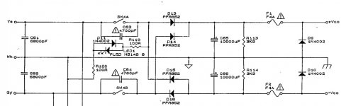
I attached the schematics of my amplifier's power supply section as a reference.
Thanks
I have an integrated amplifier (fully recaped and few more tweekings), it's mains transformer is 200VA (2x28Vac) rated and I was wondering what will be the effect of replacing it's transformer for a higher VA rating and output voltage, let's say 300VA (or higher VA rating) 2x30v output ( can't find 28V output transformers, only 25V and 30V).
I attached the schematics of my amplifier's power supply section as a reference.
Thanks
Attachments
Depends if the increase in voltage is taking the rest of the circuitry outside its voltage or thermal limits - its fairly unlikely for just 2V extra but if the design is already close to the edge that extra 7% might be bad news and impact reliability.I was wondering what will be the effect of replacing it's transformer for a higher VA rating and output voltage, let's say 300VA (or higher VA rating) 2x30v output ( can't find 28V output transformers, only 25V and 30V).
A higher power transformer will have less voltage droop under load which is probably giving a fraction of a dB more maximum power handling - and of course the transformer will run somewhat cooler.
Yes.
In principle there will be a very slight increase in power because supply will be both 3V higher and will drop slightly less ... IF new transformer has less DCR than the original one which is not guaranteed, it depends on transformer designer´s choices.
You *can* have a theoretical possible improvement of (30/28)*1.05=12.5% increase of voltage, in practice say 10% so a possible power improvement of about 20%, or not too impressing 1.5-1.6 dB or so.
In any case, 1000000 times more noticeable (and measurable) than the silly 22k resistor "differences" being argued to death in other threads")
Meaning: if you are listening and quickly switch one or the other in, you will notice something; now if somebody replaces it while you sleep and next day you turn amp on, you won´t think "WOW!!! today it sounds so MUCH BETTER than yesterday!!!"
In my view, IF you have a broken transformer, must replace it, the 300VA one is available, costs almost the same as the 200VA one and very important, it fits in the enclosure, then why not?
But if the current one is working, it´s hard to justify the size and weight increase, plus cost, freight and work involved for replacement all for a minuscule improvement.
It´s your amp and money, of course.
In principle there will be a very slight increase in power because supply will be both 3V higher and will drop slightly less ... IF new transformer has less DCR than the original one which is not guaranteed, it depends on transformer designer´s choices.
You *can* have a theoretical possible improvement of (30/28)*1.05=12.5% increase of voltage, in practice say 10% so a possible power improvement of about 20%, or not too impressing 1.5-1.6 dB or so.
In any case, 1000000 times more noticeable (and measurable) than the silly 22k resistor "differences" being argued to death in other threads
Meaning: if you are listening and quickly switch one or the other in, you will notice something; now if somebody replaces it while you sleep and next day you turn amp on, you won´t think "WOW!!! today it sounds so MUCH BETTER than yesterday!!!"
In my view, IF you have a broken transformer, must replace it, the 300VA one is available, costs almost the same as the 200VA one and very important, it fits in the enclosure, then why not?
But if the current one is working, it´s hard to justify the size and weight increase, plus cost, freight and work involved for replacement all for a minuscule improvement.
It´s your amp and money, of course.
Thanks guys.
What is the benefit of using a transformer with higher VA rating but with the same voltage output (beside cooler transformer), 28Vac in my case?
How the "extra" current delivery of a higher VA rating transformer will affect the amplifier's operation?
Another question, what will be the benefit, if any of doubling the total smoothing capacitors values from 2x10,000uF to 4x10,000uF ?
Last edited:
Extra capacitors may give louder sound, but overload the supply.
Slightly more powerful transformer MIGHT improve the sound a bit.
But the difference may not be noticeable.
Not worth the hassle.
Buy a more powerful amp, second hand they are dirt cheap.
Use this one in your den, bedroom, as a spare, whatever.
Slightly more powerful transformer MIGHT improve the sound a bit.
But the difference may not be noticeable.
Not worth the hassle.
Buy a more powerful amp, second hand they are dirt cheap.
Use this one in your den, bedroom, as a spare, whatever.
Thanks guys.
What is the benefit of using a transformer with higher VA rating but with the same voltage output (beside cooler transformer), 28Vac in my case?
How the "extra" current delivery of a higher VA rating transformer will affect the amplifier's operation?
Another question, what will be the benefit, if any of doubling the total smoothing capacitors values from 2x10,000uF to 4x10,000uF ?
You have already been answered but again: minimal almost inaudible improvement, and that only if driven LOUD
Very hard to detect.
You will NOT have any extra current delivery by any means; current "pull" is determined by the load and voltage,which in this case remains untouched.
Last edited:
Semiconductor electronics are very susceptible to temperatures when these exceed 80C. For an audio amplifier, it is wise to use far lower maximum temperatures, as high temperatures derate power transistors and increase the risk of thermal runaway. So, to increase the power rating of your amplifier you need to make sure:
a) the various amplifier components can handle the new higher rail voltages.
b) the new power handling does not increase the temperature of semiconductors beyond what they can handle.
c) the power stage's heatsink is large enough to handle the new dissipation of power.
d) the smoothing capacitors are large enough to keep the power supply ripple within limits.
e) there is enough space and ventilation for the new LARGER transformer.
f) the rectifier bridges are large enough to handle the new inrush currents and current ratings.
g) the power transistors can handle the new power.
As many have written, the benefits do not justify the expenses and the hassle.
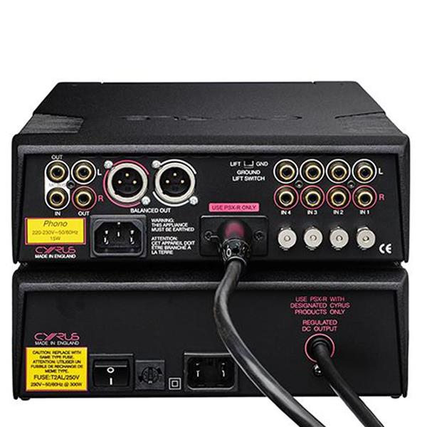
The reason that I'm asking is because my amplifier is a Mission Cyrus 2, this amplifier can be conected to an external PSX power supply (hard to find, 500VA transformer and 70,000uF total capacitance, 40Vdc output) and increase the power of the Cyrus 2 from 50W 8ohm\ 80W 4ohm to 70w 8ohm/125W 4ohm so I'm thinking about building one or just change the built in transformer to a higher rating and add more capacitors.
Last edited:
If your amplifier is designed to be used with a bigger power supply to produce more output power, it means, it is already designed to support the higher power. As you wrote, you only need to produce a bigger power supply. I understand that the 40V is the rail to rail voltage - the positive and negative voltages relative to ground both should be 20V.
Again, I assume your amplifier uses a split power supply with three terminals. If I am correct, you need a bigger transformer, a sizeable rectifier bridge bolted to a heatsink and two smoothing capacitors. If my memory serves me right, the rectifier bridge is connected with the AC terminals to the end terminals of a centred tapped secondary winding. The ground terminal is the centre tap from the transformer secondary. The smoothing capacitors should be connected as follows:
a) The positive rail side.
The capacitor's anode connected to the positive side of the rectifier and the capacitor cathode connected to ground, the centre tap.
b) The negative rail side.
The capacitor's anode connected to the ground and the capacitor's cathode to the negative side of the rectifier.
I may be wrong, but 70,000uf may not be needed. I would suggest to first use a smaller capacitance like 10,000uF per rail and do your testing.
Warning:
Like a pathological paranoid, I strongly suggest you to make sure all polarities, including all ground terminals are correct. Failure to follow polarities results in destruction of semiconductors and electrolytics.

Thanks olddiy.
IF that´s the amp we are talking about, there is NO space to "upgrade" the PT, period.
They even had to cut a notch in the main board so as not to touch it with the current one.
As of extra caps, OP might make a couple narrow boards front and back holding 4 extra caps, a pair for each rail.
Not sure sound would be impacted, since that one already looks like a well designed and proportioned amp.
Amp seems to have 40+40V rails since PT is 28+28VAC:I understand that the 40V is the rail to rail voltage - the positive and negative voltages relative to ground both should be 20V.
Last edited:
The Cyrus 2 is compatible only with the Cyrus PSX, not the PSX-r or the PSX-R2.
The PSX (1st version) output +/-40Vdc, it's transformer output is 2x28Vac.
If your amplifier is designed to be used with a bigger power supply to produce more output power, it means, it is already designed to support the higher power. As you wrote, you only need to produce a bigger power supply. I understand that the 40V is the rail to rail voltage - the positive and negative voltages relative to ground both should be 20V.
Thanks.
Rails voltage is +/-40Vdc
Your only practical option seems to build an external power supply with your requirements. The external supply should provide three terminals, a ground, a positive terminal and a negative terminal. To avoid having stray magnetic and electric fields, keep the DC lead terminals close together. You can use electric tape or a shrinkable sleeve at regular intervals along the leads.
To avoid damage make sure every polarity and voltage is correct. Power supplies do not forgive errors!
A skeletal suggestion for the power supply's architecture:
RFI_filter----->fuse----->transformer----->rectifier----->smoothing----->fuses----->leads_to_external_load
To avoid damage make sure every polarity and voltage is correct. Power supplies do not forgive errors!
A skeletal suggestion for the power supply's architecture:
RFI_filter----->fuse----->transformer----->rectifier----->smoothing----->fuses----->leads_to_external_load
Last edited:
- Home
- Amplifiers
- Solid State
- Upgrading integrated amplifier tranformer