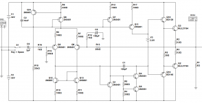
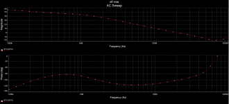
Performance is on par with the traditional EF-VAS with cascode.
Benefits
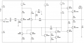
1. Current is limited out of box. No extra current limit circuitry is needed.
2. It is stable. The idea is that, at very high frequency, Q5 will be dropped out of the local feedback loop automatically without farther compensation, though I did not prove it mathematically.
Benefits
1. Current is limited out of box. No extra current limit circuitry is needed.
2. It is stable. The idea is that, at very high frequency, Q5 will be dropped out of the local feedback loop automatically without farther compensation, though I did not prove it mathematically.

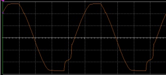
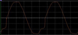
PS: The clipping behavior is no worse than original EF-VAS in blameless design.
"Honey Badger" is amplifier topology using blameless with EF2-VAS by Ostripper. The first version it have sticky clipping at 20kHz. When a resistor add at collector first VAS transistor, the clipping is good, no sticky anymore. I think Bonsai use this trick, too.
"Honey Badger" is amplifier topology using blameless with EF2-VAS by Ostripper. The first version it have sticky clipping at 20kHz. When a resistor add at collector first VAS transistor, the clipping is good, no sticky anymore. I think Bonsai use this trick, too.
I just did some simple test. Even single transistor VAS shows up sticky clipping in my simulation. Remove 8 Ohm load will eliminate the sticky behavior. I believe the issue is more than VAS along.
I probably need to look deep into this issue before copying solution from others.
This is a neat idea. I wonder if this can be used to improve marginal current mirror distortion by setting the vas input voltage unambiguously above the vbe + degeneration resistor voltage of the mirror. Selfs amplifier book said some transistors gave unexpectedly bad distortion in the basic mirror due to their vbe being higher than the vas input voltage. This could also help with the four transistor mirror for the same reason.
Can you go into more depth about why you are saying the input to q4 controls at high frequency?
Can you go into more depth about why you are saying the input to q4 controls at high frequency?
Can you go into more depth about why you are saying the input to q4 controls at high frequency?
Here is my thought.
The only high impedance (let’s say relative high impedance) node is the base of Q5. Thus, I expect Q5 will give up first at high frequency. Once Q5 gives up. It will just act like a capacitor.
Maybe that is not true. Q5 is partially cascoded, it may still functional at high frequency. Honestly, I did not fully investigate the behavior of the small loop inside Miller cap.
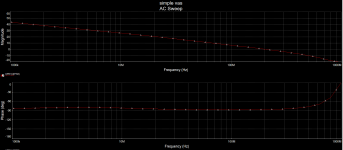
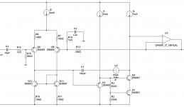
Here is my investigation regarding the stability of the local loop.
I find those frequencies below ft of the transistor are not that interesting. The gain starts to roll off around the ft.
In the simulation, the unit gain frequency is beyond 10GHz. I don't think you can reach that high in reality under DIY condition. The wave length of 10G signal is only 3cm. 1cm trace will cause enough phase shift to make the loop unstable. You'd better put every thing close together.
I am not the expert regarding this. Any suggestion?


Last edited:
Douglas Self (6th edition) did the same thing but got rid of current source I3 and reduced complexity. Maybe you might want to study/investigate?
Thanks, I will check the book.
VAS has very high output impedance, previous method using voltage source was not good choice. Injecting voltage source needs low impedance at the output point to make it work.
Now, I switch to current source, the result makes more sense to me.
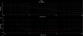
The unit current gain frequency is around 40MHz. The phase margin is around 50 degree.
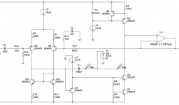
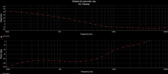
Now, I switch to current source, the result makes more sense to me.
The unit current gain frequency is around 40MHz. The phase margin is around 50 degree.


Last edited:
- Home
- Amplifiers
- Solid State
- VAS: Folded Emitter Follower with Cascode
