hi guys ,
i made this amp from a schematic a frnd shared , although i am content with this amp i dont get the crystal clear and airy highs i have felt with other amps also when i tested with square wave everything becomes fugly after 5khz , i have even reduced the miller cap but still the ultra clear highs are not present , does this amp needs a EF3 as my speakers do dip to 2.5 ohms at some frequencies ...
regards
phoenix
Attachments
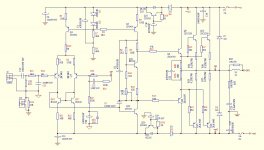
What are you using for Q8 & Q24 drivers?
I found AX6 dull & lifeless with TIP41c/42c. With MJE15028/29 the highs are fine. As good as the unavailable 2n5320/22 the amp came with, but of which a pair survive. Maybe if you have parts labeled 2sa1837/2sc4793 they are not really 30 mhz Ft parts. My MJE15028/29 are real On parts from Newark(farnell) distributor.
I found AX6 dull & lifeless with TIP41c/42c. With MJE15028/29 the highs are fine. As good as the unavailable 2n5320/22 the amp came with, but of which a pair survive. Maybe if you have parts labeled 2sa1837/2sc4793 they are not really 30 mhz Ft parts. My MJE15028/29 are real On parts from Newark(farnell) distributor.
Last edited:
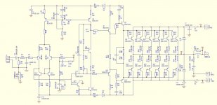
I'd add a large capacitor to ground after D4 and D6. And try without C22.
Are C5, C20, and C21 COG/NPO ?
Unless I'm going blind, where the hell is D4 and D6?
I just don't see them.
Or maybe just get rid of C9, C10. The emitter followers may be OK, as long as they're not "driving" capacitors.
A capacitance multiplier has too high an output impedance to dispense entirely with an output capacitor.
I'd lose the "capacitance multipliers" in the supply rails - they'll probably oscillate.
Could try a simple RC filter instead.
A capacitance multiplier has too high an output impedance to dispense entirely with an output capacitor.
Sorry, don't understand. The capacitance mulipliers are in the supply lines, to smooth the supply to the first stages.
Edit - ah, got it. The ef output impedance doesn't need to be all that low, as the input stages have good psrr. A small C is probably OK, but 100uF is dicey.
Edit2: if there's significant supply droop when the output stages are working hard, the emitter-followers will be starved. Just get rid of the damn' things!
Last edited:
If the input stages have good PSRR (which may be debatable), what were the capacitor-multipliers there for to begin with?
If you need another good reason to omit them, they're costing valuable output voltage swing, too -- could be in the 3 to 5V range!
I'd also suggest raising the VAS current -- 6mA is a little light; 10mA is sort of a *de facto standard*, though I can't give you the reasoning behind it. It might also be worth considering a different transistor. 2N5551/'5401 are rarely found in this duty. I think they'll have trouble keeping up, dissipation-wise.
The bias spreader needs work, too. Right now it only adjusts to about 2,8 Vbe's -- you need 4. Also suggest eliminating R3 and R46 -- degeneration is not good here. Maybe raise the other divider resistor values by x3, x5 or so. That leaves more work for the transistor, which is good since it's a lot stiffer.
Cheers
Last edited:
It might also help to split C5 between the VAS transistors. Let Q5 share a little bit of it.
Also agree with earlier poster that 220pF is a very high value. If it's presently necessary for stability, there are probably other techniques/circuit-locations that would exact less of a performance penalty.
Maybe a little degeneration would help Q23 as well. As it is, a very high-impedance node (Q6 / Q16 Collectors) is driving a very low-impedance node, Q23's Base, which gives the 220pF C5 WAY too much influence over the VAS slew rate.
Regards
edit: Lower the value of R4. The circuit is designed to set a one 1N4148 Vf drop across it: ~56 ohms will cause a ~10mA current through it. And be prepared for a change in output offset.")
Also agree with earlier poster that 220pF is a very high value. If it's presently necessary for stability, there are probably other techniques/circuit-locations that would exact less of a performance penalty.
Maybe a little degeneration would help Q23 as well. As it is, a very high-impedance node (Q6 / Q16 Collectors) is driving a very low-impedance node, Q23's Base, which gives the 220pF C5 WAY too much influence over the VAS slew rate.
Regards
edit: Lower the value of R4. The circuit is designed to set a one 1N4148 Vf drop across it: ~56 ohms will cause a ~10mA current through it. And be prepared for a change in output offset.
Last edited:
phoenix87 said:I have changed the 2n to KSc3503/1381 in the vas stage ...
Good. The C3503 / A1381 pair is a much better choice for VAS service.
Now back to a question asked earlier, "What dielectric flavor is C5?" There are many choices that will decrease sound quality.
Another of those things that I can't give you the reasoning behind: The node R49 - R50 should be disconnected from the output node (the node shared by the four output Emitter resistors). I would suspect that it has something to do with turning off the output transistors more efficiently, since it allows a little bit of negative bias.
Cheers
Last edited:
- Home
- Amplifiers
- Solid State
- help me improve on this current design