I have a 557 Power Amp that is part of a Meridian stack I bought back in 1998 or so (502, 500, 566-24, 557). It's all performed flawlessly on a daily basis since last week when my 557 turned on then promptly turned itself back off. The soft start begins as usual and the system turns on (if there is a source you can hear audio from both channels) then after a couple of seconds, I hear a click, the system mutes and the power down process starts. I removed all inputs and outputs and tested again with the same results.
I was able to find a 557 schematic and as far as I can tell, there is a DC offset tripping the DC Protection Circuit you can see at the bottom of the attached schematic. I'm getting about 250mV of DC at the P.A. out line (at C2) coming down through R8 (at C3) to the minus input of the top op amp and the + input of the lower op amp (at C4) then on to R25 (labeled DC Protection). This is causing the op amps to drive the output transistor that mutes the amp and trips the protection relay shutting the amp off. I'm thinking that one of the main electrolytic caps is bad due to the age of the amp. Has anyone seen this problem with a 557 before?
Also, there is an adjustable resistor labeled R27, VA 1111 (probably Voltage Adjust?) at position B4 in the schematic. Does anyone know if that is the DC offset adjustment? See image and schematic below in reference to description. It's an impressive protection system. Any help will be greatly appreciated.
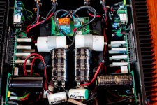
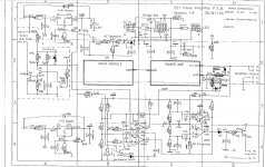
Thanks,
Dean
I was able to find a 557 schematic and as far as I can tell, there is a DC offset tripping the DC Protection Circuit you can see at the bottom of the attached schematic. I'm getting about 250mV of DC at the P.A. out line (at C2) coming down through R8 (at C3) to the minus input of the top op amp and the + input of the lower op amp (at C4) then on to R25 (labeled DC Protection). This is causing the op amps to drive the output transistor that mutes the amp and trips the protection relay shutting the amp off. I'm thinking that one of the main electrolytic caps is bad due to the age of the amp. Has anyone seen this problem with a 557 before?
Also, there is an adjustable resistor labeled R27, VA 1111 (probably Voltage Adjust?) at position B4 in the schematic. Does anyone know if that is the DC offset adjustment? See image and schematic below in reference to description. It's an impressive protection system. Any help will be greatly appreciated.


Thanks,
Dean
Last edited:
Additional Schematics
Here are the remaining schematic pages for the Meridian 557. The 250 mV DC offset measurement was at the coil L1 located at D3 on page 2 of the schematics. That P.A. out line coming from this coil is the connection that leads to R8 and the op amps in the area labeled "DC protection".
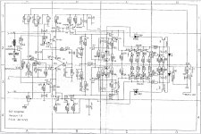
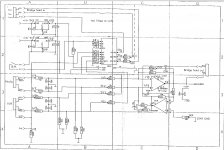
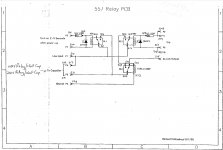
Here are the remaining schematic pages for the Meridian 557. The 250 mV DC offset measurement was at the coil L1 located at D3 on page 2 of the schematics. That P.A. out line coming from this coil is the connection that leads to R8 and the op amps in the area labeled "DC protection".


Is this 250mV on both channels or just one? I'd also check the +/-15V as this is critical for the DC protect circuit. You might also want to check the output transistor legs are properly soldered and none are a bit loose when poked and prodded - this can happen with frequent thermal cycling, a bad method to attach the output transistors if you ask me.
No, the 250mV is only on the right channel. +/-15v are both perfect. The output transistors are all good. As I mentioned, if I have an active source when the power amp turns on I can hear it on both channels before it powers down. There is a slight click on the right channel when the protect circuit cuts things off and the amp proceeds to power down.
The amp looks to be DC coupled, so you might want to check the input voltages for both channels with all the inputs/outputs disconnected. If there's a small DC offset on the input of one channel, it could well translate into a larger DC offset on the output. You can also try adjusting VR1, but measure its value first to make sure you can put it back to the original setting afterwards.
Hi,
Thank you for that suggestion which is just in time since I plan on working on it tomorrow. When you say measure the value of VR1 first, do you mean the resistance between either +15 or -15v and the variable connection with everything off or the voltage between the variable connection and ground with the amp turned on?
Thanks,
Dean
I'm doing more digging into the results I'm seeing and perhaps some of you can see something in this I'm missing. I'm measuring at the speaker outputs for DC offset now instead of the input side of L1. What I'm seeing is this.
Left: @power on == 7-9 mV, @power off, zero then rises to about 90mV then back to 0
Right: @power on == 16mV, @power off, zero then rises to about 60mV then back to 0
The channels go to zero when the safety clicks in then starts the rise a couple of seconds after I power off. I assume this has something to do with caps discharging.
These offsets don't seem that bad to me so I'm not convinced that is the cause. Does anyone know what an unacceptable DC offset threshold is for these amps?
I assume the circuit driving P6 & P7 on page 1 of the schematic (bottom-right) is the power good signal which goes to pins 6 & 7 on the relay board but I can't find what is driving P9/P11 - P8/18 (labeled "trip") to activate RL3 which cuts off the power. Can anyone point me to the location of that circuit?
It looks like R1 & R16 are good test points for V+ V- but I don't see anything regarding their nominal values. Do the amp boards have any easy to access test points for +15, -15 and ground? I don't want to short something out reaching a probe around components to find the negative side of caps.
Thanks,
Dean
Well, I found the problem and it had nothing to do with the DC offset or any failed active components. I was poking the speaker terminals from the inside of the chassis to document all the voltage and offset values and surprise! The amplifier turned on just fine. So I started inspecting the speaker terminals and by moving the wires or tightening/loosening the outer connectors I could make the amp fail or work. Clearly one of the speaker terminals must have a bad insulator that is allowing a connection between + and chassis ground. I've tweaked the terminal into working mode and OMG, it's so nice to have this amp back - this thing sounds so much better than my backup amp. I'm looking for replacement speaker terminals now. Here is something similar to the current type, let me know if anyone has found any that are extremely reliable:
https://amzn.to/3cZHpkA
Thanks,
Dean
https://amzn.to/3cZHpkA
Thanks,
Dean
Last edited:
I would use something like these
https://uk.farnell.com/pomona/6883/...-WHOOPS-Test725-maxCPA-Step1&gross_price=true
I find that the Chinese manufactured ones do not have a shoulder round the connector so you run the risk of the same problem you already have, I have found that you can put a small piece of heatshrink about 1mm long around the stud but they dont locate well so you have to line them up
Stuart
Those amazon/Chinese binding post look the same as the ones I've tried, they snap with finger tightness
KEYSTONE 4109 look nicer
An externally hosted image should be here but it was not working when we last tested it.
KEYSTONE 4109 look nicer
Last edited:
I am glad that it is solved. This things sounds very nice indeed. Good luck with terminals.
Thank you for your help, even though the problem turned out to be something else, I was following your tip with the resistor when I stumbled across the problem.
Cheers,
Dean
- Status
- This old topic is closed. If you want to reopen this topic, contact a moderator using the "Report Post" button.
- Home
- Amplifiers
- Solid State
- Meridian 557 issue (see description/schematic)