hi im hoping you guys out there can help
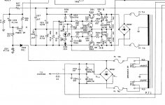
The amp i am working on at the moment, a NAD 3130 is blowing the fuses on the 24v part of the amp (f3 and f4) directly after the impedence switch.The other tappings ,29v circuit blowing fuses.
so this is what i have done so far.The transformer with the fuses out is giving 24v on both supplies.I have removed and tested all the main output transistors and diodes, these seem fine ,i havent tested the caps.the only thing im left with is thinking the transformer is faulty as when i disconnected one side of the impedence switch one side of the circuit,it didnt blow a fuse, so could it be the transformer? i dont know how to test these so some help would be great.If the transformer was faulty would it still give off the correct voltage?
many thanks
paul
Attachments
Transformers can put out correct voltage @ 1 W and as they heat up, short a turn and be incapable of full wattage.
Best way to test a transformer is 4 ohm or 8 ohm resistor of the wattage greater than twice what the amp is rated for. Pick the resistance appropriate for the rating of your amp. You can build high wattage resistors out of series parallel combinations of smaller resistors assembled on insulating board like Nema C 1/16". Or buy a 225 W 10 w resistor with sliding tap as I did 40 years ago. Ohmite or dale.
Best way to test a transformer is 4 ohm or 8 ohm resistor of the wattage greater than twice what the amp is rated for. Pick the resistance appropriate for the rating of your amp. You can build high wattage resistors out of series parallel combinations of smaller resistors assembled on insulating board like Nema C 1/16". Or buy a 225 W 10 w resistor with sliding tap as I did 40 years ago. Ohmite or dale.
testing
how do you test one of these?
Check the bridge rectifier BD501
Sid
how do you test one of these?
how do you test one of these?
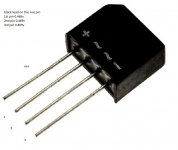
Diode Check function on a DVM, of course.
can this be done while on the board or do you have to remove?
Diode Check function on a DVM, of course.
Yes just test in situ providing you can get access.
Set your meter to Diode test then put the red lead on the -ve pin of the bridge rectifier
and the black lead on each of the ac pins in turn.
Put the black lead on the +ve pin and the red lead on each of the ac pins in turn.
Report back with the four readings you get.
BTW don't put your question in the title as it's likely to get overlooked.
Sid.
Normally you check bridge with pin names like "AC", "AC" "+" and "-".
The pins I type as "AC" have a wiggle printed next to them.
- to any other pin .001 v on diode scale is shorted.
Try to buy a bridge with more voltage (400 piv) and amperage ( 8) next time. cost cutting is for OEM's, not diy people.
The pins I type as "AC" have a wiggle printed next to them.
- to any other pin .001 v on diode scale is shorted.
Try to buy a bridge with more voltage (400 piv) and amperage ( 8) next time. cost cutting is for OEM's, not diy people.
Last edited:

Normally you check bridge with pin names like "AC", "AC" "+" and "-".
The pins I type as "AC" have a wiggle printed next to them.
- to any other pin .001 v on diode scale is shorted.
Try to buy a bridge with more voltage (400 piv) and amperage ( 8) next time. cost cutting is for OEM's, not diy people.
so something like this?
AttributeValue Bridge Type Single Phase Peak Average Forward Current 8A Peak Reverse Repetitive Voltage 600V Mounting Type Through Hole Package Type GBU Pin Count 4 Configuration Single Peak Non-Repetitive Forward Surge Current 200A Maximum Operating Temperature +150 °C Minimum Operating Temperature -55 °C Peak Forward Voltage 1V Peak Reverse Current5µA
so its simlar to testing any diode then, including how you would test a transistor?Two of the diodes in the bridge are short circuit. Replace it.
Sid
Yes, 600 v PIV is better for Eastern Hemisphere with 230 vac mains. 400 v is okay for low voltage windings in the western hemisphere. Reason for high voltage, 1300 v spikes on the AC line from Air Conditioner compressor shut off, or distant lightning strikes. 1:3 ratio of windings cuts the peak to the lower voltage windings.
200 v rating as in previous post will work "a while". Maybe original part was 200 v. shoddy.
200 v rating as in previous post will work "a while". Maybe original part was 200 v. shoddy.

- Status
- This old topic is closed. If you want to reopen this topic, contact a moderator using the "Report Post" button.
- Home
- Amplifiers
- Solid State
- NAD 3130 blowing fuses