Hi, I have a amp with STK4192 , the circuit track is broken feeding the left channel but if i run a wire connecting it, it only hums like a short, even touching the cap feeding the left side hums bad and the right side is fine,
if the amp is damaged would input side play up like it is ?
touching a wire to the left channel input cap gives a big crack on the speaker but the right working side does not do this.
Brett
if the amp is damaged would input side play up like it is ?
touching a wire to the left channel input cap gives a big crack on the speaker but the right working side does not do this.
Brett
Blown.
Replace it.
Be happy it did not take the speaker and transformer with it.
STK modules were kind of famous for that....
Change to Chinese, if original not available.
Don't change volume too fast on Chinese.
Or else alter the unit to use TDA or LM series Amps
Tedious, but in the long run worth it.
7293 or 94 will work, based on your supply volts.
Or LM 498xx, they will take +/- 100 Volts.
Heat sink mounting and wiring to suit will be needed.
On Chinese, some are good, some are bad.
On Semi has taken over Sanyo Semiconductor, and some STK seem to be in production. See if you can get from a known source.
STK were fairly high voltage types, and prone to sudden failure.
Heat sinking and close coupling to the sink with thermal grease are crucial, so is ripple in the power supply.
The 7294 is also known to explode for no reason.
So 7293 or 49810/11/30 will be more suited.
Generic 4192 on Amazon, $32 or so.
So put a 7293 (pair?), and spray all contacts, loose or noisy pots can cause enough fluctuations to blow STKs.
Or whatever the more experienced members suggest.
So put a 7293 (pair?), and spray all contacts, loose or noisy pots can cause enough fluctuations to blow STKs.
Or whatever the more experienced members suggest.
Thanks Guys,
I resoldered the ribbon wire pins on the volume control board and fitted my jumper wire
back up again and it seems to work,
The unit has already gone back to my cousins place as its got a big job at a party in a couple weeks,Haha
unit is about 37 years old now and only gets used by my aunt using the radio,
I ran it for 1 hour at half volume not problem.
@ NareshBrd How would you fit 2x 7293 as they have 15 pins into the space of the 18pin stk4192?
Brett
Obviously, not much thought went into offering a practical solution earlier but the principle of substituting 2 x similar rated mono modules for a stereo module is likely OK. Making an adaptor board to do that is a another, probably too difficult procedure though. It would be easier to strip the STK modules and their support circuits from the amp and fit a pre-assembled stereo chip-amp kit module based on good ol' reliable LM3886. That's going be cheaper and sound better than any replacement STK module.
It may be that there's no problem with the amp modules since you found it was in the wiring connections to the volume control board instead. I'd wait and see what all the fault(s) really are before offering help based guesswork. At least the party should bring on more of the problems that have been mounting over the years.
Anyway, I'd look around to borrow a backup amplifier so that the party doesn't wind up a fiasco when the music dies again. Then you can solve those problems properly and re-cap the whole amplifier too.
Ian, the 4192 is maxed out at +/- 52.5, the 3886 can take +/- 47.
So he will have to check.
As for the change of chip, I have a Sony set with working display, no output, got it for $1.5, 9 kilos or so at the local flea market.
It is supposed to have a STK 403-100 chip and a cooling fan, I have not opened it to check for a long time.
The STK modules are two amps with common power supply and mute, the other in/out pins are not common.
So basically a tedious job like I said, mounting the mono amps higher on the heat sink, and wiring the appropriate wires to the PCB.
The 7293 will run cooler than the STK I hope, and if needed a PCB can be fabricated, and a ribbon cable used to connect to the original .
I have not considered what happens if pins are left open.
Also, I don't think he has mentioned make and model.
At that age, some serious TLC is needed..
The alternative you suggest would mean a long hard look, because the input selectors, tone control and the rest of the amp may be on the same PCB, meaning that replacing the whole PCB is going to be even more work.
If he can afford it, buy another one cheap, as it is mostly used as a radio, if this sounds difficult.
Last edited:
@Ian yes there are two backup amps now I got this one going.....against my thinking my cousin found another amp the same model and purchased it for the main amp, Me I would have put that money towards a new amp. but never mind......
@NareshBrd its a poineer DC-Z93 was purchased new around 1985, yes I think that was why the hum as input was open circuit on left channel, not sure why my jumper wire did not work the first time.....thats got be stumped......its working for now
quick video showing some broken tracks on the RCA input board
DC-Z93 RCA input board repair - YouTube
It seems that the problem is corrosion if the copper tracks disintegrate like that. I would remove any old flux or grime covering the solder and inspect all the joints and copper tracks in the vicinity with a strong light and magnifier, as this problem may be general and only get worse over time, so its better to make sure this won't just recur with other tracks.
I'm not sure why it takes so long for this type of problem to emerge but in this case, it is likely the flux or washing solution residues from the original assembly process that are the cause. Sometimes, the cause is spilled drinks, cats pee or cleaning sprays finding their way into the ampifier but the corrosion is often self-sustaining and creeps along the tracks until whole lengths turn to powdery copper compounds which don't conduct at all. It will be a subcontractor rather than Pioneer who were responsible for slack assembly processes but after some 35 years, pointing the finger at some long-gone manufacturer isn't going to do much.
Tracks such as for DC power, ground and output, are the important ones for basic functionality and are usually, but not always thicker than others tracks carrying only signal and control voltages. You can get some idea of fault areas from just looking at where the current flows and what DC voltages are present on the module, relative to what should be there from the schematic or just the published module app. notes.
The recommended and max. supply voltages for STK4192 are significantly different at +/-35 V and +/-52V respectively. I doubt Pioneer or any other Japanese manufacturer would have provided power rails that reached even +/- 45V unloaded, accordingly. The OP can check this out anytime, assuming he has a multimeter.Ian, the 4192 is maxed out at +/- 52.5, the 3886 can take +/- 47.......So he will have to check.......
The power output spec. for the Pioneer product is 60W/8R so there really isn't much need for 50V rails but there will be perhaps 5% allowance for typical local mains power supply and component variations.
My Sony is marked +47 and -46 for a STK 403-90, (the limit I think was 50 volts or so) in the service manual...it seems they went close to the limit, and in my group whenever a Sony TV came in, we would put higher amp transistors, they used to fail, and destroy a lot of other parts.
We used to put 15 Amp instead of 4 Amp transistors in the SMPS, failures due to voltage fluctuation were too common, and the Trinitron design was a bit difficult to repair.
That said, Pioneer is well known, and now in a degrading board, I would ask that the PCB be washed clean with soapy and plain water, then inspected, repaired, and after testing be coated with a circuit board spray, or insulating varnish, to protect it from atmospheric corrosion..
If repaired, clean off the flux with isopropyl alcohol, that also is corrosive.
The corrosion could simply be because the OP lives in a place near the sea, or in a place with a corrosive atmosphere.
Last edited:
A possible way to replace STK modules would be to fit a replacement amp kit higher up on the original heat sink, after removing the heat sink provided with the kit, and wire it up off the original PCB..
That would be easier, but the risk of fake chips is there it seems.
At voltages that suit LM3886, it would be easy, and I doubt it will be used at high output level most of the time.
A spray of contact cleaner on all pots and switches is recommended.
And of course, change the caps if needed, Gainclone circuits seem to use higher values than older circuits.
Last edited:
@Ian, I thought is was weird for the corrosion to be under the lacquer, is wasnt just at the solder joint some times it was half way, and what was even weirder id this input board was under and protected by the main board so you think it would have less corrosion, I forgot to post the voltage at the power amp pins,
Pins
1: -.32
2: -.32
3: 0
4: -36.3
5: 0.0 went up to 0.8 I think when jumper wire hooked up
6: -42
7: -42
8: -42.8
9: -43
10: 0
11: +42.9
12: +40.8
13: 0
14: -43
15: -1.3
16: 0
17: -0.2
18 -0.2
after this repair Im sorta keen on a small basic high power 2 channel amp project is the TDA7293 fit that build or is there another cheap chip to use....
Brett
@NareshBrd sorry mate I missed page two here, the heat sink is huge and I wish now I took more picture to show you guys, yes I used my "electrical clean and lube" on the pots,
my last post question is for you also about a small basic amp project ?
Brett,
PS. sorry my posts are slow uploading they get moderated first
my last post question is for you also about a small basic amp project ?
Brett,
PS. sorry my posts are slow uploading they get moderated first
As you describe it, that's where the manufacturing process and cleaning agents themselves are the problem, rather than exposure to heat and contamination in use. The lacquer isn't a problem in itself but it traps contaminant chemical residues and these remain, creeping their way between the copper, paper/phenolic PCB and lacquer layers by capillary action and chemical reaction.@Ian, I thought is was weird for the corrosion to be under the lacquer....
Admittedly, I haven't seen many audio boards affected this way but a lot of cheap colour TVs that were produced for distribution in tropical climates in the 1980s developed such problems but usually well beyond their warranty period.
You have a choice of new build or modifying the existing one, it is quite old, maybe the transformer might be useful for the new one.
Assuming it is a fresh build, take a look at the FM module combinations sold by Salcon and Monty in India for some hints. The prices will make you smile.
Keltron capacitor kits are more expensive because those are good quality Sprague licensed capacitors, much more expensive than Chinese capacitors.
75 Indian Rupees are about 1 US Dollar.
Then decide how big your room or open plot is in area, and see how many watts you need.
Then go about choosing from the many circuits available here in this forum, and decide whether it is better to buy new or do it yourself.
Then source the parts, and cabinets, add some sweat, and you will have a unit you can say you made yourself.
As for the Pioneer set, you are now faced with removing the lacquer, repairing the board, then coating it again.
At least the lacquer kept dust off the tracks, preventing atmospheric corrosion.
It is your call...
To start with you can get a 12-0-12 transformer, run the pre amp from 0-12, and the power amp from the +/- 12...about 19 volts or so...2030 or 1875 in gain clone, those are about US 2.5 each per module.
Here Philips used 0-14-28 windings on their combination sets, cassette-tuner-amps.
You can even use a computer power supply.
The possibilities are endless, be creative.
Or just buy from a sale, or find a car set from a scrap yard, though those are no fun.
Depends on your budget, skill levels, and the time you are prepared to spend.
As for the Pioneer set, 7293 or 498xx are the only ones I can think of that will work, the 3886 is max rated to +/- 47 volts, but safe ratings are around +/- 38 to 42 volts, close enough really to what you have in place.
The 7293 will take +/- 60, the 498xx +/- 100, so they are a safer choice.
There are so many 3886 circuits here, and there must be links to PCB sources too.
Enjoy
Ohmssssss
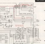
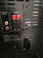
one other question guys.....
the output for the rear speakers in the circuit diagram shows a direct tap from the front speaker line output but 16 ohm load,
its odd to get a 16ohm speaker easily (we dont have any rear speakers) and if you did you would have 5.33 ohm load on the output with a 8 front and 16 rear which would be below its 6 ohm rating ?
you would need 24 ohm rear speaker to stay safe or run them in series ?
Brett
Attachments
- Home
- Amplifiers
- Solid State
- stk4192 very low to no output left channel