I've been developing amps based (very loosely) on this topology. See A small Class-H Lateral MOSFET amplifier
In order to turn Q326 and Q330 on reasonably quickly, so the rail switcher can respond to fast transients, there's a bit of juggling between Q326/330 Vbe and the relative values of R352 and R356. When it's on song, with Q322 not turned on the base of Q326 is reasonably close to its threshold.
If you've substituted transistors in this part of the circuit, you may have simply used ones with lower Vbe threshold. If you're absolutely certain everything else is fine, swap a lower value in for R354 (or a higher one for R352), and see if the rail swith shuts off then.
So besides driving me insane (is that progress).
I have split the problem - on the right hand channel:
I removed Q328 and Q322- and thus have 60v on the collectors of the outputs -Q324 is still installed- this is the -ve rail.
On the +ve rail I have left Q322,Q326 and Q330 installed and have 90v on the collectors.
I then compare the functioning left channel +ve rail (60v on collectors) voltages for the transistors:
LHC:
Q325 b 57.8/e 88.5/c57.8 and b to e 0v
Q331 b88.4/e84.5/c83.6 and b to e 0v
which suggests both transistors are off, and thus no 90v to the output collectors
RHC Q326 b 84.6/e84.4/c84.3 and b to e -0.6v
Q330 b to e is -3.4v
and so switched on and thus 90v to collectors
I am about to replace R354 which has a 3v voltage drop across it (on the LHC is is 1v) and R356 which also has a 3v voltage drop across it (LHC 0.1v).
thanks for looking- I think these devices get turned on by current, but everything seems to measure fine.
0v across R352 tells us that Q322 is off and also that there is no emitter-base current through Q326. Q326 and Q330 should both be off. Voltage on their collectors should be 60v. If there is 90v on the collectors then the fault has to be with Q326, Q330, R354 or R356.
I noticed that on the schematic for the later version there is a capacitor (100pF) between B-C of Q326.
Problem with oscillation perhaps?
Hope this helps.
Sid
I noticed that on the schematic for the later version there is a capacitor (100pF) between B-C of Q326.
Problem with oscillation perhaps?
Hope this helps.
Sid
Hi Sid
thanks it certainly does. I had not considered oscillation, but will have a look at that later today. The challenge is that the same thing is happening on the -ve rail as well, and this is all only on the right hand channel.
This has led me to looking at either the bias circuitry (Q334, R348, SVR302, R350) or the over current detection Q336 and associated resistors. Though all of these test as they should. My other theory is that there is some noise that is causing Q326 and Q330 to switch to the higher voltage, as they should, when they detect a peak (not sure how this is done other than it involves Q322 as detector)- except the noise is constant rather than instant (perhaps the oscillation?)
I measured Q326 b to e and this was -0.6v and on q330 b to e -3.4v, where as they should both be 0v.
thanks gain, any assistance appreciated greatly
Neither the bias or over current can affect the operation of this part of the circuit.
Ignore the negative rail (keep it disabled) until the positive is resolved.
My understanding of how it works is as follows:-
when the output voltage is low eg 0v the junction of R336 and R340 will be held at 7.3v by the zener ZD306. This forces Q322 to be reverse biased with D326 protecting the B-E junction. So Q322 is off and therefore Q326 and Q330 are off.
When the output voltage rises to approx 55v Q322 will start to go from reverse to forward biased. As it turns on it will then turn on Q326 and Q330.
C316 and R324 will help to speed up the switching of Q322 when the output voltage changes quickly.
good luck.
Sid
thanks Sid, I think I understand how this works now.
I have 7.3v at the junction of R336 and R340. At the base of Q322 I have 57.9v. At C320 I have 85v at the junction with R352, and 55v at the junction with R340. D326 is new and I have 57.9 at the base of Q322 and 58.6 at the emitter of Q322.
so what can be moving it to forward bias?
I compared the base of Q322and Q321 with the scope- they are the same, and Q306 base and emitter dont seem to have any noise on them. The FFT of the output shows no oscillation.
thanks again
Peter
Hi Sid
R356 starts at -2.4v and rises to -5.7, and was continuing to rise
R354 starts at-2.1v and rises to -5.07v and then seemed to stabilize
both of these were at the 0.6amp level which is the high side of the idle for these amps (usually around 0.5amp ).
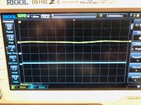
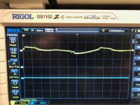
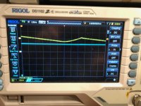
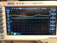
the oscilloscope pictures are:
1311- Q326 Collector only
1312- Q326 collector only
1313 Q326 collector and base
1314 collector and base
Thanks again Sid
R356 starts at -2.4v and rises to -5.7, and was continuing to rise
R354 starts at-2.1v and rises to -5.07v and then seemed to stabilize
both of these were at the 0.6amp level which is the high side of the idle for these amps (usually around 0.5amp ).
the oscilloscope pictures are:
1311- Q326 Collector only
1312- Q326 collector only
1313 Q326 collector and base
1314 collector and base
Thanks again Sid
Attachments
Does R352 still have 0v across it when R354 has 5.07v across it. If that's the case then the current through R354 must be going through Q326 B-C. This would suggest the problem is with Q326.
Looking at the scope pictures at first didn't seem to tell us much but I notice that the waveform on the third photo is cleaner than that on the second.
Is this the classic case of it's oscillating but stops when you put the scope probe on?
Repeat the scope tests with the timebase increased (lots). Make sure there is no averaging going on due to scope settings.
I'm running out of ideas now!
Sid
hi Sid
I replaced Q326- even though it was new.
and then I realized- I had replaced the 1302 and 2381 outputs with new MJE 1302A and 2381A, both of which are black with small writing- and yes I had put a 2381 as Q330- a very basic error on my behalf, exacerbated by the number of times I had stared at it.
So thank you Sid, for your help- I was starting to think I was going even more crazy
Peter
- Status
- This old topic is closed. If you want to reopen this topic, contact a moderator using the "Report Post" button.
- Home
- Amplifiers
- Solid State
- NAD 2200 wrong rail voltages