There was a similar question 13 years ago, which got no replies, so I'm going to tell my story, and hopefully someone will take pity on me and engage with me.
I was getting some miscellaneous hums and pops in my UK 240V NAD 7020N (single main board, power amp supply on the speaker connector sub assembly), so I recapped most of the larger electrolytic caps, but during the process, I put C901 (1000uF, 35V) in backwards (I know, stupid). When it powered up, it blew one of D901 or D902 (not surprisingly). I did not have any BAV19s to hand, so I just grabbed a couple of matching diodes with apparently similar values, replaced C901 (again) and both diodes, and was very relieved to find the receiver powered up OK.
All was well for a couple of months (and was sounding good), but suddenly it started just humming on both channels rather than playing music.
When I opened it up again, and powered it on, it was clear that R901 (10R 1/2W) was burning. As this is the same part of the power system as the previous fix, I took out D901 and D902, and found one had failed shorted, and was feeding AC to the tuner.
As I had actually bought some BAV19s, I replaced D901, D902, and C901 again, and also R901.
This made the receiver work again, but I thought I'd put it on the bench for a while and soak test it while it was out.
After a couple of hours, a faint mains hum started, which proceeded to get louder and louder, and the volume dropped. Shortly after that, a sweet, rather sickly smell started to come from the transformer, and on feeling the transformer, it was quite hot (around 50C when I used a thermometer).
I checked all of the components I had changed again, but everything still seemed good.
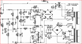
I guess that the lacquer on the transformer or the coils was breaking down, and that something was shorting in the transformer. When I measured the AC voltages (after removing the DC fuses), I found that the AC to the power amp was only showing 22.1V AC on both halves compared to the centre tap (supposed to be +-29V DC after rectification and smoothing, and the AC to the pre- and feeded amp was showing 17 and 14V (suppose to be +29.13 and -23 after rectification and smoothing). The AC voltage to D901 and D902 is only 7.2V.
I believe the windings should be 35-0-35 and maybe 30-0-30, but I don't know what the supply to the receiver part should be. I guess from the value of the zener D903 (15V) that it should be 18-20V after rectification.
The service guide is no real help.
Something is screwy in the transformer (I always knew it was failing, because there was a faint mechanical hum for some time before the failure), but there are no 2nd hand parts around at the moment (not that old ones are likely to be much better). I was considering putting a toroidal in for the power amp, and doing something else for the other parts of the supply, but not having definitive values for the different circuits, I am unsure of what I can do.
What I really need is someone to confirm the AC voltages and power ratings on the transformer, so over to you, whoever reads this thread.
I was getting some miscellaneous hums and pops in my UK 240V NAD 7020N (single main board, power amp supply on the speaker connector sub assembly), so I recapped most of the larger electrolytic caps, but during the process, I put C901 (1000uF, 35V) in backwards (I know, stupid). When it powered up, it blew one of D901 or D902 (not surprisingly). I did not have any BAV19s to hand, so I just grabbed a couple of matching diodes with apparently similar values, replaced C901 (again) and both diodes, and was very relieved to find the receiver powered up OK.
All was well for a couple of months (and was sounding good), but suddenly it started just humming on both channels rather than playing music.
When I opened it up again, and powered it on, it was clear that R901 (10R 1/2W) was burning. As this is the same part of the power system as the previous fix, I took out D901 and D902, and found one had failed shorted, and was feeding AC to the tuner.
As I had actually bought some BAV19s, I replaced D901, D902, and C901 again, and also R901.
This made the receiver work again, but I thought I'd put it on the bench for a while and soak test it while it was out.
After a couple of hours, a faint mains hum started, which proceeded to get louder and louder, and the volume dropped. Shortly after that, a sweet, rather sickly smell started to come from the transformer, and on feeling the transformer, it was quite hot (around 50C when I used a thermometer).
I checked all of the components I had changed again, but everything still seemed good.
I guess that the lacquer on the transformer or the coils was breaking down, and that something was shorting in the transformer. When I measured the AC voltages (after removing the DC fuses), I found that the AC to the power amp was only showing 22.1V AC on both halves compared to the centre tap (supposed to be +-29V DC after rectification and smoothing, and the AC to the pre- and feeded amp was showing 17 and 14V (suppose to be +29.13 and -23 after rectification and smoothing). The AC voltage to D901 and D902 is only 7.2V.
I believe the windings should be 35-0-35 and maybe 30-0-30, but I don't know what the supply to the receiver part should be. I guess from the value of the zener D903 (15V) that it should be 18-20V after rectification.
The service guide is no real help.
Something is screwy in the transformer (I always knew it was failing, because there was a faint mechanical hum for some time before the failure), but there are no 2nd hand parts around at the moment (not that old ones are likely to be much better). I was considering putting a toroidal in for the power amp, and doing something else for the other parts of the supply, but not having definitive values for the different circuits, I am unsure of what I can do.
What I really need is someone to confirm the AC voltages and power ratings on the transformer, so over to you, whoever reads this thread.
A quick search takes you to this link,
NAD 7020 noise on left power amp
, and there you have another link with the (very complete) service manual.
http://p10hifi.net/planet10/manuals/NAD7020early_servMan.pdf
What is not very helpful ?
NAD 7020 noise on left power amp
, and there you have another link with the (very complete) service manual.
http://p10hifi.net/planet10/manuals/NAD7020early_servMan.pdf
What is not very helpful ?
R901 leads to a regulator involving Q901 feeding the tuner section to see if the preamp and power amp sections are still working.
You can disable that supply by taking R901 out of circuit. Use a pair snips to cut one of the leads at a 45 degree angle. In that way the ends will overlap and touch when you bend them back later so you can solder the joint. If the preamp and power amp sections work then check the components connected to Q901 to see if there have been any failures.
You can disable that supply by taking R901 out of circuit. Use a pair snips to cut one of the leads at a 45 degree angle. In that way the ends will overlap and touch when you bend them back later so you can solder the joint. If the preamp and power amp sections work then check the components connected to Q901 to see if there have been any failures.
NAD transformers often have hum, that is not indicative of faulty.
But if it has overheated and had the typical smell of burning wire enamel, it could have shorted out some windings. I did not find an exact description of it, then you will have to deduce it by Ohm's Law (if you decide that it is the problem and want to replace it, but that is something very difficult because of the specific secondary windings for LEDs, lighting, etc.
Only a similar discarded device could work, it is an amplifier of many years.
The total consumption of the receiver says 150 Watts. The input fuses to the main diode bridge (they are not D901 and D902, so 7.2 volts may be fine. The power fuses are listed as 250 volts and the fusing amperage depends on the model (which we do not know)
It could be approximated by Ohmn's Law, remember that the DC values (rectifier output) correspond to the AC value multiplied by 1.41 .......
A quick search takes you to this link,
NAD 7020 noise on left power amp
, and there you have another link with the (very complete) service manual.
http://p10hifi.net/planet10/manuals/NAD7020early_servMan.pdf
What is not very helpful ?
When I said not very helpful, I meant for my particular problem. I have spent several days trying to find the information I asked for, and I don't appreciate being pointed at information I've already looked at, although you were not to know that.
I had downloaded that service manual before you pointed it out, and while it describes the amp, gives great schematics and part lists, and provides bias and set-up information, there is nothing in it that answers my question of what is the output voltages and power of the transformer secondaries. I've been working from the circuit diagram in that document for some time.
I've also read the thread you point out. Again, nothing that helps my problem.
I said in my original post that it is a UK 240V NAD 7020N, which means that it is wired as an E2 or E3 power supply according to the schematic.
By basic PD that I've sorted out myself, I'm pretty certain that the problem is the transformer, as there is no way that a bridge rectifier given AC 22.1-0-22.1 will deliver +29 and -29V, as shown on the schematic.
With regard to your later post, I don't know whether trying to work out the parameters of a potentially faulty transformer using ohms law is likely to give me reliable figures.
I can make informed guesses about the voltages from the schematic for the power amp windings, and the pre and feeder amp windings, but I'm less sure about the tuner feed, as there are no voltages shown on the diagram.
The hum is just part of the problem, and affects all inputs, not just the tuner. I believe that the biggest problem is the low voltages from the transformer. I don't believe that that was the original issue, but something has happened while I have been working that I think has damaged an already ageing transformer.
...there is no way that a bridge rectifier given AC 22.1-0-22.1 will deliver +29 and -29V, as shown on the schematic.....
AC 22.1-0-22.1 through FWB to large caps should make 31.254VDC minus diode losses. 29V is not real wrong.
I do think your low-voltage supply is sick.
Yes, find out why your low voltage supply is bad - it is likely the source of overload that is overheating the transformer. To exonerate the transformer, disconnect the secondaries entirely, and put a dim bulb tester in series with the mains. Use a low wattage bulb - 60 watts. It it glows any more than just a dim orange on the filament you have a shorted turn somewhere. If it doesn’t, it is fine. It would be unusual in my experience for a transformer to fail if it were getting to only 50C. Internal temp may be higher, but virtually anything will safely get to 100C for at least a few excursions even with normal magnet wire. I’ve had transformers smelling pretty bad buzzing like crazy, and not sitting level anymore still pumping out amps while making lots of hydrogen (wasting the college’s electricity). And the one on one of my old Flame Linears got blistering hot when all the output transistors failed short. Way more than 50C. It still runs (with new D424 outputs).
You’re in a place where you have 50Hz power, right? Transformers will buzz more and run hotter at 50 Hz than at 60, even if they are 50 Hz rated. If the buzz is really annoying or the trafo does turn out to be bad I might think about using a toroid as a replacement and figuring out how to mount it. They tend to be quieter.
You’re in a place where you have 50Hz power, right? Transformers will buzz more and run hotter at 50 Hz than at 60, even if they are 50 Hz rated. If the buzz is really annoying or the trafo does turn out to be bad I might think about using a toroid as a replacement and figuring out how to mount it. They tend to be quieter.
..............I was getting some miscellaneous hums and pops in my UK 240V NAD 7020N ...............
Ops, I hadn't realized that UK equals United Kingdom, and I read lightly. I thought it was some complete description of the model !
.... and I don't appreciate being pointed at information I've already looked at, although you were not to know that.
That is not the point. The point is that I wanted to help you, and when I placed the link to the service manual, I fulfilled the part that was my turn, according to your own request:
" ..... so over to you, whoever reads this thread. "
I also help the other participants so that they can join your request more quickly, by saving them work that was your turn.
Good luck with the repair.
Last edited:
I believe that the biggest problem is the low voltages from the transformer. I don't believe that that was the original issue, but something has happened while I have been working that I think has damaged an already ageing transformer.
Maybe an electrolytic capacitor turned backwards? , the low-voltage winding of the transformer carries thin wire ......
Thank you for your suggestions.
Whilst there was AC going into the tuner, I've fixed the diodes and capacitors, so there is no AC now, and when I first powered it up, there was no hum, that developed in the hours following the last repair.
The voltages that I measured were at the transformer end of the fuses (there are fuses on both sides of the low voltage windings) with the fuses removed. This means that there was no load on the secondaries, and 2 x 22.1 V AC will not produce the specified +- 29V for the power amp, ditto the pre and feeder supply. With the voltages low with no load, I'm pretty sure the problem is in the transformer.
The receiver has been shelved for the time being (my wife cannot stand the smell of the burning enamel), but if anybody can come up with the expected voltages, I would be very grateful.
@acedemia50
Thank you for your posts. I appreciate that you help many people, but I tried posting as much information as I had already worked out, in the hope that people replying might realise I was not just someone with no electronic experience, and not suggest things I had done in my basic PD.
I appreciate that the reverse capacitor was a bad mistake, but I felt that including that information, even though it was embarrassing, was important. I've worked in a service centre (software support, not electrical), and I know that what people don't tell you is often more important than what they do!
The receiver had been working for a couple of months after I rectified that mistake. The diode failing a second time was unexpected, but after that was replaced, the receiver still worked, and the current problem happened in the soak test that followed (what a soak test is supposed to do).
If and when I revisit getting this receiver working again, I will post here again, in case it helps anybody in the future.
" If and when I revisit getting this receiver working again, I will post here again, in case it helps anybody in the future.
That's the attitude, I'm glad about that.")
The mistake you made cannot be considered anything shameful, it can happen to the most experienced technician. I understand that you took it for granted that everyone here is an expert, but it is not so. Nor am I, but a portion of my studies were recorded and I never forget a teacher's comment:
"Who knows Ohm's Law, knows electronics, and they will be able to solve many problems with it" Which by the way is not only the famous memory aid triangle, it is much more extensive, but with a full understanding of these three basic but fundamental values, It has a very valuable help when some values are missing, as this is the case. In any case, a "perfect" repair is difficult, trying that the result is physically like the original, for what I already mentioned, it will not be easy to get an original replacement transformer today, I sincerely hope that you will achieve it, here in my country it would be almost a miracle .......
But if you don't care about the interior appearance, you can always feed the low-voltage section of the tuner with a smaller conventional source.
Greetings and good luck again !
That's the attitude, I'm glad about that.
The mistake you made cannot be considered anything shameful, it can happen to the most experienced technician. I understand that you took it for granted that everyone here is an expert, but it is not so. Nor am I, but a portion of my studies were recorded and I never forget a teacher's comment:
"Who knows Ohm's Law, knows electronics, and they will be able to solve many problems with it" Which by the way is not only the famous memory aid triangle, it is much more extensive, but with a full understanding of these three basic but fundamental values, It has a very valuable help when some values are missing, as this is the case. In any case, a "perfect" repair is difficult, trying that the result is physically like the original, for what I already mentioned, it will not be easy to get an original replacement transformer today, I sincerely hope that you will achieve it, here in my country it would be almost a miracle .......
But if you don't care about the interior appearance, you can always feed the low-voltage section of the tuner with a smaller conventional source.
Greetings and good luck again !
When I measured the AC voltages (after removing the DC fuses), I found that the AC to the power amp was only showing 22.1V AC on both halves compared to the centre tap (supposed to be +-29V DC after rectification and smoothing,
and the AC to the pre- and feeded amp was showing 17 and 14V (suppose to be +29.13 and -23 after rectification and smoothing). The AC voltage to D901 and D902 is only 7.2V.
There are +29 + Volt and -26 - Volt regulated connecting to various points in the circuit. The power transistors have +/-29 Volt supplies.
You have to look at the voltage regulator set up and see what is wrong there.
Attachments
Long time no update.
Well, I found a cheap spares-or-repairs 7020 that was in a quite bad physical state, but the transformer looked OK.
Performed the transplant, and ended up with a working receiver. Yay!. No humming, and the transformer was running nice an cool. So it was the transformer.
But...
After several months of happy listening, I forgot to turn it off after listening to a few albums, and it was left running idle for a couple of hours. Suddenly the house was filled with the same smell of burning enamel that went with the first transformer failure, and when I checked the mains fuse had blown.
Now, I know that the 'new' transformer was actually a similar age to the original one, but does anybody have any thoughts on whether I was unlucky and just picked up another failing transformer (or maybe they just have a limited life), or whether I should look at the electronics again. It seems too much of a coincidence to have a similar failure.
One thing I did not do was to re-align the output stages after recapping the receive and replacing the transformerr. Is it possible that this could have caused more current draw from the transformer, and thus cause the transformer to fail? I find it unlikely, as the 'new' transformer was running cool before it failed.
I have a transformer from a 3020 (it doesn't have the lower voltage windings for the radio or dial light, but should be close enough to drive just the amp, and I actually bought it before I found the scrap 7020), but I am reluctant to try it if is thought that there could be a fault elsewhere in the receiver.
I'm currently using a 7020i (with the digital tuner), but I just don't think it sounds as good, and I'd like to get the 7020N up and running again.
Thanks,
Peter.
The probability of "something" wrong within the amplifier is very high.
I would say swapping out the original transformer with a similar surrogate transformer sort of proves this idea.
Besides this; do you have any power conditioning on the mains where you plug-in for power?
Do you know if your AC outlet provides clean, stable voltage + frequency?
I would say swapping out the original transformer with a similar surrogate transformer sort of proves this idea.
Besides this; do you have any power conditioning on the mains where you plug-in for power?
Do you know if your AC outlet provides clean, stable voltage + frequency?
I think the probability that the replacement transformer suffers from the same fault (manufacturing defect ? hummm) as the original is highly unlikely.
Some circuit component of the power supply and/or power amplifier stage causes overheating and destruction.
The diode bridge and supply capacitors should have been tested, the quiescent current of the output TRs adjusted, the rail voltages checked, etc., before using the amplifier again. When a component is damaged by excess current (the one that caused the overheating and destruction of the power transformer) it is because something in another part of the circuit causes the problem, people with no experience in electronics do not understand that you always have to find out the cause, the original components are generally very noble, they do not fail because they are calculated with tolerance margins, a simple burnt resistor should not be replaced without finding out why it burned.
"A resistance failed, I put a bigger one" is the typical response of an inexperienced technician who will have to give explanations when the "repaired" device returns to his workshop.
In this case, the overheated and damaged output transformer is the consequence, not the source of the failure.
Good point. Sometimes the mains voltage can be out of spec on the high side. In the US the ANSI spec is 120 +/- 5%, so 126V in the max. I know this is rare but I've seen it twice in my time. Worst was a friends house where one leg went up to 180V and the other down to 60V due to a bad neutral at the pole. Needless to say, he lost a few items. Worth checking....Do you know if your AC outlet provides clean, stable voltage + frequency?
- Home
- Amplifiers
- Solid State
- NAD 7020 transformer