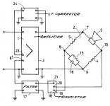
At the output of bridge current comparison circuit and the voltage across the speaker. Used in the 70s. (1973)

This circuit reminds Korn's US patent # 3 647 969 filed in 1969.
As in the above circuit, the differential output signal of the bridge was handled
by a bipolar transistor. It shows an analogy with op-amps used later in the same
kind of bridge circuits.
Image from Korn's patent :
Paul Voigt (not Voight) is quoted here :
Commercial motional feedback woofer available sort of
Attachments
Last edited:
Experience in implementing EMF for displacement.
Опыт реализации ЭМОС по смещению. Часть 1
Опыт реализации ЭМОС по смещению. Часть 1
For a long time I had the notion of measuring cone position etc by laser interferometry. (about which I know little) One person I consulted said I would need a stabilised helium-Neon laser at least a metre long to get enough phase coherency. That's going to be tricky to fit into most furnishing schemes.
I have no idea if that is correct. I was hoping to use laser diodes.
I have no idea if that is correct. I was hoping to use laser diodes.
ЭМОС в низкочастотном звене АС
...EMF can only correct the movement of the voice coil and has absolutely no control over all other moving parts of the loudspeaker. This fact is really often left out of brackets when designing EMF systems. All intermediate elements are left out of consideration, and it seems that the signal from the sensor is directly the sound pressure of the system. However, it is not. The difference between the signal from the sensor and the sound we hear is determined by a number of intermediate elements, such as: a diffuser (a distributed surface that does not have absolute rigidity), an edge corrugation, a centering washer, a dust cap, voice coil flexible leads, a diffuser holder. In addition, the vibrations of various parts of the acoustic design (box), always present, remain. All these imperfect elements in a real speaker make their negative contribution - additional nonlinearity and noise, which cannot be corrected by the sensor EMF, since they are outside the feedback loop. Therefore, to achieve the best results with such an EMF system (close to the Hi-End requirements), you should initially choose high-quality (and these are, as a rule, expensive) heads, with a large linear stroke, with a high mechanical strength of the moving system, with a rigid diffuser, capable of working at frequencies below their own resonance with small extraneous sounds due to the above factors. The quality of workmanship and thoughtfulness of the acoustic design also play an important role. In the case of using heads of poor quality or an unsuccessful case design, the time and money spent on manufacturing and adjusting the EMF may not morally pay off and not bring the desired satisfaction from the result obtained.
...EMF can only correct the movement of the voice coil and has absolutely no control over all other moving parts of the loudspeaker. This fact is really often left out of brackets when designing EMF systems. All intermediate elements are left out of consideration, and it seems that the signal from the sensor is directly the sound pressure of the system. However, it is not. The difference between the signal from the sensor and the sound we hear is determined by a number of intermediate elements, such as: a diffuser (a distributed surface that does not have absolute rigidity), an edge corrugation, a centering washer, a dust cap, voice coil flexible leads, a diffuser holder. In addition, the vibrations of various parts of the acoustic design (box), always present, remain. All these imperfect elements in a real speaker make their negative contribution - additional nonlinearity and noise, which cannot be corrected by the sensor EMF, since they are outside the feedback loop. Therefore, to achieve the best results with such an EMF system (close to the Hi-End requirements), you should initially choose high-quality (and these are, as a rule, expensive) heads, with a large linear stroke, with a high mechanical strength of the moving system, with a rigid diffuser, capable of working at frequencies below their own resonance with small extraneous sounds due to the above factors. The quality of workmanship and thoughtfulness of the acoustic design also play an important role. In the case of using heads of poor quality or an unsuccessful case design, the time and money spent on manufacturing and adjusting the EMF may not morally pay off and not bring the desired satisfaction from the result obtained.
Loudspeaker with EMF (Troshin N.)
Громкоговоритель с ЭМОС (Трошин Н.) | ldsound.ru
Громкоговоритель с ЭМОС (Трошин Н.) | ldsound.ru
For a long time I had the notion of measuring cone position etc by laser interferometry. (about which I know little) One person I consulted said I would need a stabilised helium-Neon laser at least a metre long to get enough phase coherency. That's going to be tricky to fit into most furnishing schemes.
I have no idea if that is correct. I was hoping to use laser diodes.
#23
Kitekat
")
EMOS for displacement. Ten years later.
Alexander Rakitsky, Izhevsk
ЭМОС по смещению. Десять лет спустя - LM317, LM337, LM1117, NE5534, TL072
Last edited:
- Status
- This old topic is closed. If you want to reopen this topic, contact a moderator using the "Report Post" button.
- Home
- Amplifiers
- Solid State
- Where to put feedback loop in amplifier?