Curious, I went to Jensen' website. From the JT11P1 pdf, and from the faq, I found these:
-The core material is "Custom Nickel/Molybdenum/Iron Alloy". If we use Ferrites (easier for me to get here) will it shows quite the same behavior?
- input impedance 13kohm at 1khz, DC resistance 1.45kohm
In the 11p1.pdf, I dont see any voltage figures. All in dB. How to translate this dB figure into how many voltage RMS the transformer can handle?
lumanauw said:Curious, I went to Jensen' website. From the JT11P1 pdf, and from the faq, I found these:
-The core material is "Custom Nickel/Molybdenum/Iron Alloy". If we use Ferrites (easier for me to get here) will it shows quite the same behavior?
I don't think ferrite will work well at all at audio frequencies.
In the 11p1.pdf, I dont see any voltage figures. All in dB. How to translate this dB figure into how many voltage RMS the transformer can handle?
Most of the figures are in dBu, which is decibels referenced to 0.7746 volts.
To figure out RMS voltage, take the dBu figure and divide by 20. Then take 10 to the power of the result. Finally, multiply by 0.7746.
For example, the 11P-1 is rated for a maximum input of 20dBu at 20 Hz.
So, 20/20 = 1. 101 is 10. 10 x 0.7746 is 7.746 volts RMS.
By the way, CineMag makes transformers which as near as I can tell are every bit as good as Jensen but for significantly less.
Check 'em out.
se
Hi Lumanauw!
Yes, if caculate with cm^2 and Gauss..... , then you will need
the factor 10exp8....
I usually work with SI units m, m^2, Tesla instead of Gauss etc...,
so I do not need unit related multiplication factors.
(Please note 4.44 is derived not from units but from
pi x (square root of 2)....)
I can confirm your calculations and you can easily see, why I stopped my efforts when I wanted to go for larger signals below 20Hz.....
My proposal of 1V/40Hz were absolut minimum requirements, for a
suitable transformer.
If you wish some db headroom against standard 0db levels, as discussed above, and lower frequencies then you will need more turns.... or a bigger core....
I agree that ferrite is definitely not a fortunate choice for this.
Especially if you pick standard power materials as N27 or similar, then you get comparably low permeabilities and with this especially at low frequencies the XFR coupling is coming low and inductance also.... If you pick high perm ferrites then you must not press them
very much... If you press them, their permeability drops... Already normal mechanical work, metal clamps or glue can result in poor results... Also take care about the remaining gap, already a 50µm gap brings down the inductance if you use high perms...
May be the proposal of JOAN2 is good. Silicone Steel is easily available and offers high saturation. ...but losses at higher frequencies are poor... If you try this, I would propose to look for a core set which offers very thin blades.
Wire size of 0.1mm is easily sufficient, you could go even for thinner wires, but below 0.1mm it is difficult handle!!!
Also isolation properties are getting less at small diameters.
Bye
Markus
Does this mean you have gotten your samples Steve? Do tell!By the way, CineMag makes transformers which as near as I can tell are every bit as good as Jensen but for significantly less.
Maybe we should use ordinary sheet metal core instead of ferrites, like SE wrote why. Here I can only buy the ordinary power transformer core. The ones for audio transformer (here called H14) is very rare.
Mr. Pass himself uses ordinary power transformer for load in his ZEN V7-T, not using special transformer with special material. And he reported good results.
First step. How can I know the number of windings or inductance needed? JT11P1 can handle 7.7Vrms at 20hz. Is this hard to achieve? From the photo the completed xformer is not so big.
If DIY resulting bigger than Jensen, its OK with me, the sound quality is first, size doesn't matter.
There is no connection between Faraday equation and final xformer impedance? Faraday is for knowing the number of turns for certain xformer working condition. No impedance figure here.
Impedance figure is the bridge for connecting this device to other device. Impedance is known by manual measurement? So what if the number of turns from Faraday equation differs with impedance measurement?
Here I have RLC meter. How to measure "impedance"? R+L?
tiroth said:Does this mean you have gotten your samples Steve? Do tell!
Not yet. I said "near as I can tell" based on what I've seen of them and their legacy. Right now I'm up to my eyeballs working on some cables so won't be getting around to getting anything from CineMag for a while yet. Probably a few more weeks.
se
Nelson Pass said:One advantage of ferrite cores is that they don't suffer
from Eddy currents.
sorry, couldn't resist.
I gotcher ferrite cores right heah, pal! :grabcrotch:
Sorry, couldn't Pass that up.
")
se
The required numbers of turns are depending on the allowed flux density, the core cross section area and the time voltage product.
This is independed from the inductance.
The inductance depend from the permeability of the material.
The inductance then gives the inductive part of the transformers impedance. If you look at the transformer itself, then you can model the losses by two resistors. One in series with the inductance, this models the copper resistance of the wire. I would expect that we can neglect this compared to the required inductive portion.
The second resistor is in parallel with the inductance and models the losses in the core. Unfortunately these losses are depending very much on the frequency. Well in ferrites they would be quite low, as eddy currents in the ferrites are low in the audio frequency range... as Nelson Pass already stated.... also hysteresis losses are low in ferrites...
If we go for ordinary 50Hz power cores the frequency depending losses will be comparably high. I have no idea, if it would still work.
Please note that these loss models are very much simplified.
In fact the core losses do not exactly increase with the square of the applied voltage like the resistor would.
Measuring the inductance should work with a standard LCR meter.
The copper resistance can be measured with a standard Rdc measurement. The resistance which the RCL meter will display is giving a mixture of both resistors and will probably depend very much on the measuring frequency of the LCR meter.
Such line transformer is n interesting thing, but you may need several steps of trial and error.
Ans yes.... 7.7Vrms at 20hz as the JT11P1 can handle is difficult to meet.
@DJK:
Thanks for pointing out that you assumed much higher imbalance than 1 Ohm.
I agree, if we pick a simple topology with 1/2 NE 5532 then it will be hard to achieve higher common mode rejection than 40db.
But already 40 db is a step forward.
The best which I could achieve (ten years back ) with a simple , but carefully balanced circuit was 56 db at 50Hz.
....do you have also experience with that instrumentation amplifiers which use 3 OP amps to set up one amplifier with high common mode rejection? I never tried them....
Bye
Markus
This is independed from the inductance.
The inductance depend from the permeability of the material.
The inductance then gives the inductive part of the transformers impedance. If you look at the transformer itself, then you can model the losses by two resistors. One in series with the inductance, this models the copper resistance of the wire. I would expect that we can neglect this compared to the required inductive portion.
The second resistor is in parallel with the inductance and models the losses in the core. Unfortunately these losses are depending very much on the frequency. Well in ferrites they would be quite low, as eddy currents in the ferrites are low in the audio frequency range... as Nelson Pass already stated.... also hysteresis losses are low in ferrites...
If we go for ordinary 50Hz power cores the frequency depending losses will be comparably high. I have no idea, if it would still work.
Please note that these loss models are very much simplified.
In fact the core losses do not exactly increase with the square of the applied voltage like the resistor would.
Measuring the inductance should work with a standard LCR meter.
The copper resistance can be measured with a standard Rdc measurement. The resistance which the RCL meter will display is giving a mixture of both resistors and will probably depend very much on the measuring frequency of the LCR meter.
Such line transformer is n interesting thing, but you may need several steps of trial and error.
Ans yes.... 7.7Vrms at 20hz as the JT11P1 can handle is difficult to meet.
@DJK:
Thanks for pointing out that you assumed much higher imbalance than 1 Ohm.
I agree, if we pick a simple topology with 1/2 NE 5532 then it will be hard to achieve higher common mode rejection than 40db.
But already 40 db is a step forward.
The best which I could achieve (ten years back
) with a simple , but carefully balanced circuit was 56 db at 50Hz. ....do you have also experience with that instrumentation amplifiers which use 3 OP amps to set up one amplifier with high common mode rejection? I never tried them....
Bye
Markus
Problem no.1 is not solved yet. What core should we use? The choice is 2, one is ferrites, two is ordinary sheet metal power transformer core.
SE and a peek at Jensen suggested that we do not use Ferrites. This is confusing.
Is this about ferrites in general, or Mr.Pass is suggesting to use Ferrites for DIY line transformer?One advantage of ferrite cores is that they don't suffer from Eddy currents.
SE and a peek at Jensen suggested that we do not use Ferrites. This is confusing.
I think for a line signal XFR the high perm materials will be the better choice. But I would not say that high perm would generally be the right choice for high quality. ....especially not if you look to power applications....
@Lumanauw:
Eddy currents do also exist in ferrites, but at audio frequencies they are very low.
For your decision:
-Your stores do not offer high perm ferrites in the required size. The larger ferrites which you could get are for flybacks and will provide lower permeability. In fact you would face a hard battle to achieve the required inductance without real exzessive number of turns.
-You could try ordinary sheet metals.
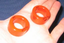
-I had a look to my assortment and found two torroids of an amorphous metal manufactured by the VAC.
They provide high perm, high flux, low losses. But winding will be difficult as they are torroids. Please refer to the link.
I have two cores of the type W376 on hand.
In order to wind several hundred turns on this core you could
first wind the required wire length to a thin wooden stick.
I.e. 8mm diameter 30 cm length..... and then rewind from this primitive "magazine" to the torroid.
For the proposed torroids I would start first trials with about 500 turns. This will allow 2.5V signal at 20Hz and provide an inductance of about 5H (which is still very low). If you manage higher number of turns ..., fine....
I am also attaching an image of that cores.
You can send me your adress to [[EMAIL ADDRESS REMOVED BY MODERATOR]] and I will send the two cores.
www.vacuumschmelze.de/dbw/public_vac/Resources_pdf/File?id=pdf_Pk003_d.PDF&name=Pk003_d.PDF
Bye
Markus
@Lumanauw:
Eddy currents do also exist in ferrites, but at audio frequencies they are very low.
For your decision:
-Your stores do not offer high perm ferrites in the required size. The larger ferrites which you could get are for flybacks and will provide lower permeability. In fact you would face a hard battle to achieve the required inductance without real exzessive number of turns.
-You could try ordinary sheet metals.
-I had a look to my assortment and found two torroids of an amorphous metal manufactured by the VAC.
They provide high perm, high flux, low losses. But winding will be difficult as they are torroids. Please refer to the link.
I have two cores of the type W376 on hand.
In order to wind several hundred turns on this core you could
first wind the required wire length to a thin wooden stick.
I.e. 8mm diameter 30 cm length..... and then rewind from this primitive "magazine" to the torroid.
For the proposed torroids I would start first trials with about 500 turns. This will allow 2.5V signal at 20Hz and provide an inductance of about 5H (which is still very low). If you manage higher number of turns ..., fine....
I am also attaching an image of that cores.
You can send me your adress to [[EMAIL ADDRESS REMOVED BY MODERATOR]] and I will send the two cores.
www.vacuumschmelze.de/dbw/public_vac/Resources_pdf/File?id=pdf_Pk003_d.PDF&name=Pk003_d.PDF
Bye
Markus
Attachments
Hi, ChocoHolic,
Thanks for the offering. I take "high permeability" material is a material with few windings already got high inductance?
Which have higher permeability, ferrites or sheet metal core?
In the local shop here I can find not-ordinary materials, like kool-U from mag-inc, various metal (dont know what inside, but metal), but they are all in toroidal shape. I've tried winding on small toroid, very-very difficult. So, in this project, E cores are my option.
Hi Lumanauw,
Ferrites for power applications typically show rel. permeability between 2000 and 3000 and max flux density between 0.3T...0.45T.
High perm ferrites show typically 10 000 ...20 000, but after real life handling (glueing, pressure etc, some remaining gap if a two core pieces have to be combined...) you can be lucky if you get effective values close to 10 000. Max flux density is typically lower than for power ferrites, about 0.25T...0.4T ...depending on material and temperature.
The material of my torroids is Vitroperm 500F (nano cristalline material from VAC) and offers a permeability around 20 000. Max flux densitity is around 1.1T.
Ordinary sheet metals show rel perms in the range of 3000 and 5000, I think.
Max flux density is around 1T.
I have heard of materials with rel permeabilities up to 100 000, but
I have no idea about the name or the manufacturer and also not if all the other material properties would work for a line XFR.
I am not aware of high perm materials, which could serve our purpose just with a few tunrs. You would need extremly high permeability combined with extremly high max flux density to achiev this.
.... you will probably have to wind a lot of turns.....
Often it is not showed, which rel. permeability the material has, but the AL value of the core.
L = AL x N^2
Good Luck and looking forward to your results
Markus
Hi, ChocoHolic,
Thanks for the info. So power ferrites and sheet metal cores doesnt differ so much in their permeability? Meaning using whichever will result in quite the same number of turns?
The first step I will take is hunt for available E cores. I will buy power ferrites and sheet metal cores in a couple of days. When I get the cores, I will report the size, to determine the winding number.
Problem no.2. The diameter of wires. What size will be in this project? It is only for line signal. I think about 0.1mm. Is it too big?
Hi!
....back again....
Sheet metals allow higher flux densities, so you will need less turns here.
0.1mm is probably thicker than what you require.
To thick? Well, not optimzed. Smaller would probably be better.
But thinner wires are difficult to handle (without good equipment).
You may face broken wires...
Bye
Markus
- Status
- This old topic is closed. If you want to reopen this topic, contact a moderator using the "Report Post" button.
- Home
- Amplifiers
- Solid State
- DIY signal line transformer ?