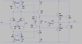
Wonder about this bias solution for dual mirrors, any comment why and why not?
Seems to bee a solution to the Slone dual mirror dilemma.
R1=R2 and R3=R4 if feedback current*R=0,6 or there abt then the diode-copled transistors could bee dropped.
Seems to bee a solution to the Slone dual mirror dilemma.
R1=R2 and R3=R4 if feedback current*R=0,6 or there abt then the diode-copled transistors could bee dropped.
Attachments
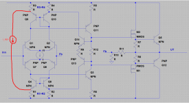
I think it should work, but the circuit is incomplete. You need a reference current. In any feedback circuit you need a reference, a forward path and a feedback path.
In your case,
- Forward path: the current mirrors, Q3, Q11
- Feedback path: R12, Q13, Q14
- Reference is missing
I drew in red where you can add the reference current source I_REF.
You can work out the relationship between I_Q3, I_Q11 and I_REF.
----
EDIT:
I just saw you wrote, R3 > R4 and R1 > R2. In that case you are using the tail current sources (partially) as I_REF. I guess that works too.
Attachments
Last edited:
I think it should work, but the circuit is incomplete. You need a reference current. In any feedback circuit you need a reference, a forward path and a feedback path.
In your case,
- Forward path: the current mirrors, Q3, Q11
- Feedback path: R12, Q13, Q14
- Reference is missing
I drew in red where you can add the reference current source I_REF.
You can work out the relationship between I_Q3, I_Q11 and I_REF.
----
EDIT:
I just saw you wrote, R3 > R4 and R1 > R2. In that case you are using the tail current sources (partially) as I_REF. I guess that works too.
Ypp, reference current via R9 therby stabilizing vas current.
The hurdle is what you haven't drawn a practical schematic for yet - I1; a current source which must operate with -1.2V across it. Easier to tie the emitters of Q7/Q6 to the + rail and Q1/Q2 to the - rail with independent CCS's.
Current sorse also just drawn as princip, and sorce is sorce regardless of voltage
")
So therfore your asumtion fails.
Also if input transistors is swapped with jfet the current corce can bee just a simple resistor.
Last edited:
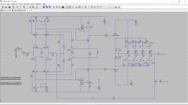
The voltage between the bases of Q9 and Q10 is essentially set by the extra feedback loop, so replacing R35 by something else should in principle only change the bias current of the second stage, not the quiescent current of the output stage. To set the quiescent current of the output stage, you could add an adjustable VBE multiplier in series with R35, but outside the feedback loop involving Q9 and Q10, or replace R3 with some adjustable temperature-compensating thing.
To compensate the thermal drift and bias adjust, will you replace the R35 with voltage multiplier +2 resistors?
NJL are old generation, they have been replaced by NJW , but LKA showed me better NJW0281/0302 .
Q9 and Q10 shuld take care of the termal compensation.
yes output's is draved with old stoc.
The prinsie of using mos as driver with current multiplier was my point.
The input cap for the mosfets become a cap and stabilzing load.
So why replace R35? if using a bias circuit here the feedback is in general lost.
And the vas current stabilezing lost () (?)
The voltage between the bases of Q9 and Q10 is essentially set by the extra feedback loop, so replacing R35 by something else should in principle only change the bias current of the second stage, not the quiescent current of the output stage. To set the quiescent current of the output stage, you could add an adjustable VBE multiplier in series with R35, but outside the feedback loop involving Q9 and Q10, or replace R3 with some adjustable temperature-compensating thing.
But changing the bias of second stage also changes bias of output stage
Changing R35 with diode + resistor stil gives the current feedback but less feedback, and reduses termal compensation for second stage not output as voltage @ bases of Q9 and Q19 is setting voltage also for output stage.
() (?)
Samuel Groner also has a solution in his website.
Thank you !
Havent seen that before, obvius several things to consider here.
Finally it became clear. Current mirrors became unstable. Two mirrors can also be considered as two modulated current sources. If you choose to half-modulate the sources, you will have the same amount of current available for common mode suppression. almost "magical". I appreciate all input.
Close to 1 1/2 mirror.

Close to 1 1/2 mirror.
Last edited:
Look here for some nice ideas: http://www.ne.jp/asahi/evo/amp/J200K1529/report.htm
tnx, been there.Look here for some nice ideas: http://www.ne.jp/asahi/evo/amp/J200K1529/report.htm
I am thinking about the amount of local feedback for the bias setting, so the vas section to be stabile, seem to bee (!!). The "gain of feedback of it " since the drivers also seems likely to bee werrry important. caused by variation inthe Fe / Hfe of next , if it is ever possible to make current mirror two sied, symmetric, jet i stil vonder how . Maybee half mirror. i have tested prackticsetup and that did work, somhow better than expeckted
- Home
- Amplifiers
- Solid State
- Symmetry and why not dual mirror ?