Hi all:
I am working on restoring a 45 year old BGW 750A amplifier which had been retired from service at Universal Studios, having proudly been part of the "Sensurround" revolution.
The amplifier was stated to "work but occasionally go into protection", which I assumed was due to inadequate heat dissipation as both the thermal switches for the (really loud) fan had been disconnected and the thermal grease on the output transistors had become thick & cruddy with age. I am replacing the mica insulation and the thermal grease on each of the output transistors and installing a new quiet DC brush-less fan.
Each channel has 10 NPN 2N3773 devices. Using my cheap transistor checker, I got the following hFE/Uf readings:
Channel A
1. 55/470 6. 55/489
2. 44/490 7. 51/494
3. 73/499 8. 59/485
4. 63/490 9. 82/490
5. 55/488 10. 48/498
Channel B
1. 59/490 6. 44/485
2. 24/494 7. 25/494
3. 112/494 8. 34/493
4. 22/489 9. 55/499
5. 99/494 10. 62/489
Questions:
[a] Could the variation in hFE be the cause of the amplifier heating up and going into protection?
I presume the 2N3773 transistors were matched at the factory, is it normal for these output transistors to drift with age, akin to the small signal input differential pairs?
[c] And finally, should I replace these with modern (closer matched) Onsemi devices?
Hope everyone is staying healthy & safe.
Rgds
Mayank
Last edited:
Member
Joined 2009
Paid Member
I imagine they would’ve been matched for Vbe rather than hfe, the variation of which maybe normal for process tolerances where and when they were made. Cause of overheating maybe poor bias control, bias too high, heatsinking too poor, dust build up, poor ventilation due to installation etc. - lots of possible reasons.
That wouldn’t cause overheating. Operating it without a fan would since it can’t convection cool very well (needs some air flow). The small electrolytics need to b replaced anyway, regardless of whether they are causing a problem NOW or not.
I’ll bet they didn’t match the output transistors, but they did select them for voltage. If you do ever need to replace them use MJ15024, so you don’t have to select them for voltage.
I’ll bet they didn’t match the output transistors, but they did select them for voltage. If you do ever need to replace them use MJ15024, so you don’t have to select them for voltage.
Thank you for your comments and advice. As all 20 2N3773 transistors test OK (slight variation in hFE), I will not replace them at this stage.
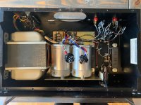
Inside of the chassis is now looking clean & presentable - it was detailed using nylon brushes and my 3 gallon air compressor. Very happy to see no sign of rust or metal discoloration. No dust bunnies remaining.
Starting with internal cooling - thermal switches and fan. The original fan Cyclohm Model 3450 is made from solid cast metal frame weighing in over 1.1 lbs drawing 0.4 A and rated at 25 W. It appears that at the factory they had cutoff the frame on the side to accommodate the chassis mounted M2 terminal strip (see picture below). Because of this, one cannot do a simple "drop-in" replacement with a modern 120 mm computer case fan. I have fabricated a bracket out of sheet metal to fix a new slightly smaller 95 mm brush-less DC fan. This will run continuously with a separate power supply.
Attachments

Just placed an order with Mouser - I will be replacing all existing 45 year old tantalum and electrolytic capacitors ... and the high wattage carbon dep resistors.
Rgds
Mayank
Rgds
Mayank
You have a early 750A. We did not match the 2N3773 outputs. New thermal grease and Mica's is needed, make sure to replace all old caps and check big electrolytics also look for matched ripple under load. I was the VP of eng @ BGW. Duke
Wow.
Appreciate the comment & historical perspective Duke.
You and your team at BGW were true pioneers in bringing surround sound !!
I am really looking forward to restoring this amplifier to its former glory.
*bowing down in reverence*
Mayank
Appreciate the comment & historical perspective Duke.
You and your team at BGW were true pioneers in bringing surround sound !!
I am really looking forward to restoring this amplifier to its former glory.
*bowing down in reverence*
Mayank
Last edited:
Corona lock down update:
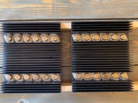
I have completed the process of carefully removing all the output devices, cleaning the heat sink, scrubbing out the old hardened compound and replacing each of the 24 TO-3 transistors (20 2N3773 outputs and 4 drivers) with new mica insulators and fresh heat sink compound.
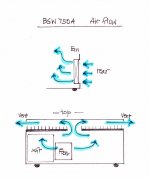
The original cooling design used the two speed fan to draw in cool air through the rear of the chassis, pass it under the bottom part of the heatsinks and then have the air pass via the heat sink fins to exhaust it through both sides of the unit. I've tried to draw the airflow diagram attached herewith.
Question for Duke and others: Would the thermal dissipation/cooling improve if the air flow was now "reversed" by turning the new DC fan around? This would suck in fresh cool air from the side vents on the top, force it over the heat sink fins, down inside the chassis to finally exhaust it through the rear of the unit.
Rgds
Mayank
I have completed the process of carefully removing all the output devices, cleaning the heat sink, scrubbing out the old hardened compound and replacing each of the 24 TO-3 transistors (20 2N3773 outputs and 4 drivers) with new mica insulators and fresh heat sink compound.
The original cooling design used the two speed fan to draw in cool air through the rear of the chassis, pass it under the bottom part of the heatsinks and then have the air pass via the heat sink fins to exhaust it through both sides of the unit. I've tried to draw the airflow diagram attached herewith.
Question for Duke and others: Would the thermal dissipation/cooling improve if the air flow was now "reversed" by turning the new DC fan around? This would suck in fresh cool air from the side vents on the top, force it over the heat sink fins, down inside the chassis to finally exhaust it through the rear of the unit.
Rgds
Mayank
Attachments
Last edited:
Hi Mayank
The fan should exhaust the air. The air intake is then much lower velocity (Many of open holes) and will pick up less dust.
Duke
The fan should exhaust the air. The air intake is then much lower velocity (Many of open holes) and will pick up less dust.
Duke
I just wanted to circle back and close the loop on this thread.
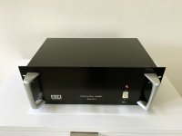
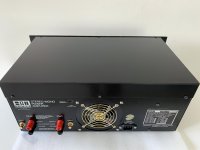
The restoration and rebuild of this wonderful amplifier is finally complete. I am enjoying listening to it in my main living room set up. So clear, extremely quiet and with earth-shattering lower end (true to it's Sensurround moniker). As a burn in test, I left it on for 48 hours and was impressed to find the heat sinks just slightly warm to the touch.
Here are some final pictures of the restoration, before and after I screwed in the freshly painted top cover.
Thank you Duke and all who helped me with their valuable comments, suggestions and encouragement.
Very thrilled with its performance!
Rgds
Mayank
Attachments


Last edited:
- Home
- Amplifiers
- Solid State
- BGW 750A - output transistors