Hi, I have a question to the greater tech-heads out there..
I just finished recapping and refreshing my old NAD 2140 amplifier yesterday. It was working fine, correct readings on the outputs, etc. Just as I was about to mount the chassis back on, I wanted to calibrate the idle current as instructed in the service manual - please find it here: https://audio-circuit.dk/wp-content/uploads/simple-file-list/ssmn/NAD-2140-pwr-sm.pdf
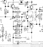
So I had connected one multimeter probe to the + terminal of the left channel, and held the other probe against the TP1 test point. Thinking of it afterwards I should have used clips or soldered a wire, because what happened was that I slipped and shorted between the TP1 point and the middle leg of transistor Q623 (SanKen 2SC2921). Visible flash of light and a pop, and frustrated of my carelessness I quickly unplugged the thing.
So now I noticed that the fuse called "F3" had blown. All other components look intact and unaffected. I thought replacing the fuse would be enough to get it all back to normal, but it keeps blowing when powering.
So my question is, which parts am I looking to test and maybe replace? My initial thought was the Q623 transistor since that's where the short occurred, and to my (limited) knowledge it seems to be connected to the F3 fuse. Is there any way I can test this transistor? I'm worried I will cause more damage to the circuit if I turn it on now. I'm still pretty new to this, so if someone with a better eye for schematics can instruct me where to go next that would be greatly appreciated. Like I said, all the caps are new and replaced. I'd rather not hand it in to a repairman, since I came so far myself before this mishap.
Have a blessed Sunday!
I just finished recapping and refreshing my old NAD 2140 amplifier yesterday. It was working fine, correct readings on the outputs, etc. Just as I was about to mount the chassis back on, I wanted to calibrate the idle current as instructed in the service manual - please find it here: https://audio-circuit.dk/wp-content/uploads/simple-file-list/ssmn/NAD-2140-pwr-sm.pdf
So I had connected one multimeter probe to the + terminal of the left channel, and held the other probe against the TP1 test point. Thinking of it afterwards I should have used clips or soldered a wire, because what happened was that I slipped and shorted between the TP1 point and the middle leg of transistor Q623 (SanKen 2SC2921). Visible flash of light and a pop, and frustrated of my carelessness I quickly unplugged the thing.
So now I noticed that the fuse called "F3" had blown. All other components look intact and unaffected. I thought replacing the fuse would be enough to get it all back to normal, but it keeps blowing when powering.
So my question is, which parts am I looking to test and maybe replace? My initial thought was the Q623 transistor since that's where the short occurred, and to my (limited) knowledge it seems to be connected to the F3 fuse. Is there any way I can test this transistor? I'm worried I will cause more damage to the circuit if I turn it on now. I'm still pretty new to this, so if someone with a better eye for schematics can instruct me where to go next that would be greatly appreciated. Like I said, all the caps are new and replaced. I'd rather not hand it in to a repairman, since I came so far myself before this mishap.
Have a blessed Sunday!
Last edited:
Sadly we see this all to often... a recap gone wrong... but the good news is that it should be an easy fix and a good chance to learn.
You will almost certainly have zapped the output transistors, and from your description of what you did it is quite possible Q623 is actually OK (because the middle leg is the collector and therefore connected to the power supply) and that it is the lower one of the pair that has failed... however... you are probably looking at replacing both output devices and their respective driver transistors. The 0.22 ohm emitter resistors need careful checking to make sure they have not gone open circuit or high in value. The 180 between the base's of the output pair needs checking.
If and when you power up again then use a DBT (dim bulb tester) as that will save further catastrophic damage in the event there are other issues. The bias also needs turning to minimum before you switch on again.
Hi Mooly,
Thank you for the swift reply - yes I'm actually quite mad because it was running so nice and I was just about to do the final touch-up...
So, am I looking at checking the QC23 and the QC25 - together with their driver transistors, i.e. Q615 and Q617? And what do you mean when referring to the 180? Sorry, maybe some baby language is in place here.
I'm now watching some vids of DBT usage to learn how to use one. And lastly, how do I turn down the bias?
Thanks a lot for your informative reply.
The bias is controlled by VR603 and VR604. The 500 ohm preset needs to be turned to maximum resistance (500 ohms) to give minimum bias.
Have you actually checked the output transistors for shorts by reading between C and E and seeing if either device reads low ohms or short circuit. I suspect they will.
Have you actually checked the output transistors for shorts by reading between C and E and seeing if either device reads low ohms or short circuit. I suspect they will.
Hi again;
With all of the four output transistors disconnected from the board, this is the readings I got between C and E.
Q625: Somewhere around 1.1-1.6 MOhms
Q623: OL
Q624: OL
Q626: OL
Did the diode-meter test as well and these are the readings I get, if that helps:
Q625
Positive Lead to Base, Negative Lead to Collector = 0.003 V
Positive Lead to Collector, Negative Lead to Base = 0.003 V
Positive Lead to Base, Negative Lead to Emitter = OL
Positive Lead to Emitter, Negative Lead to Base = 0.51 V
Q623
Positive Lead to Base, Negative Lead to Collector = 0.52 V
Positive Lead to Collector, Negative Lead to Base = OL
Positive Lead to Base, Negative Lead to Emitter = 0.53 V
Positive Lead to Emitter, Negative Lead to Base = OL
Q624
Positive Lead to Base, Negative Lead to Collector = 0.52 V
Positive Lead to Collector, Negative Lead to Base = OL
Positive Lead to Base, Negative Lead to Emitter = 0.53 V
Positive Lead to Emitter, Negative Lead to Base = OL
Q626
Positive Lead to Base, Negative Lead to Collector = OL
Positive Lead to Collector, Negative Lead to Base = 0.53 V
Positive Lead to Base, Negative Lead to Emitter = OL
Positive Lead to Emitter, Negative Lead to Base = 0.54 V
Sorry, maybe excessive information above, I'm learning so that's why I posted all of it.. Seems the Q625 is the one that differs from the pattern. I am a little unsure though why the 2SA1215 transistors (Q625 + Q626) seem to give an inverted value compared to the 2SC2921 ones (Q623 + Q624). Since according to datasheets they are all in the direction B-C-E (if you face them from the PCB-side).
Regarding the emitter resistors, they read 0.2 Ohms, so they should be in good shape, right? The resistor R655 also reads 180.2, so that one is good as well.
Last edited:
Hi again Mooly, I posted the results in previous post. Also tested the Q615 and Q617, giving me the following:
Q615
Positive Lead to Base, Negative Lead to Collector = 0.63 V
Positive Lead to Collector, Negative Lead to Base = OL
Positive Lead to Base, Negative Lead to Emitter = 0.63 V
Positive Lead to Emitter, Negative Lead to Base = OL
Q617
Positive Lead to Base, Negative Lead to Collector = OL
Positive Lead to Collector, Negative Lead to Base = 0.63 V
Positive Lead to Base, Negative Lead to Emitter = OL
Positive Lead to Emitter, Negative Lead to Base = 0.63 V
So these are also inverted in that way, so I guess that's how it's supposed to be.
The fault seems to be in Q625 then?
Best regards,
Arvid
Q625 is definitely zapped.
The other readings look OK although I haven't examined each in detail.
The NPN devices (arrow on emitter pointing out) are polarity opposites of the PNP's (emitter arrow pointing inward) and so that is why the readings are inverted.
The service manual shows MJ type devices which are common and should be readily available... but don't buy semiconductors off ebay as many are fake.
Last edited:
Q625 is definitely zapped.
The other readings look OK although I haven't examined each in detail.
The NPN devices (arrow on emitter pointing out) are polarity opposites of the PNP's (emitter arrow pointing inward) and so that is why the readings are inverted.
The service manual shows MJ type devices which are common and should be readily available... but don't buy semiconductors off ebay as many are fake.
Okay, many thanks. Is there any other part in the chain that is important to check? I will try to track down a genuine replacement for that one.. Is the one above (Q623) good or should I change that one as well to be safe?
Those MJ type connectors look quite different, do I just hook up two legs?
Thanks a lot so far, really helpful.
Last edited:
I was going off the service manual you posted a link too which shows... lets have a look... MJ15003 and MJ15004 which are round T03 devices.
The Sanken is a different package (an MT-200) so you are going to have to stick to those.
Digikey list the NPN but the PNP 2SA1215 is not available:
https://www.digikey.co.uk/products/en?keywords=2SC2921
I can't just think of any alternatives off hand for those, I'd have to give that some thought later.
I was going off the service manual you posted a link too which shows... lets have a look... MJ15003 and MJ15004 which are round T03 devices.
The Sanken is a different package (an MT-200) so you are going to have to stick to those.
Digikey list the NPN but the PNP 2SA1215 is not available:
https://www.digikey.co.uk/products/en?keywords=2SC2921
I can't just think of any alternatives off hand for those, I'd have to give that some thought later.
Yes shame they were sold out at Digikey. If someone reading this has got spares of authentic Sanken 2SA1215 that would be very appreciated
")
It might be worth you starting a new thread in parts and asking if anyone knows of any available complementary pairs in the MT-200 outline as suitable replacements for the original types.
Digikey have a PNP device in stock, the 2SA1494 but not its complement which would be the 2SC3858. You can use non complementary parts if it came down to it.
Digikey have a PNP device in stock, the 2SA1494 but not its complement which would be the 2SC3858. You can use non complementary parts if it came down to it.
What do you say about this, genuine? Seems shipping costs will totally kill the price though, as I live in Sweden.
2SA1215
As always, it depends whether the device is genuine or not. They do say they are an authorised distributer so no reason to doubt at this stage.
Ebay is the place to beware of, semiconductors and caps fakes are rife.
This is an old thread but still being posted to:
My Transistors, original or copy?
As always, it depends whether the device is genuine or not. They do say they are an authorised distributer so no reason to doubt at this stage.
Ebay is the place to beware of, semiconductors and caps fakes are rife.
This is an old thread but still being posted to:
My Transistors, original or copy?
Hi again Mooly, I managed to track down an original spare part from a local technician. Will solder everything back into place, have double-checked that the drive transistors, nearby resistors are OK.
Just a stupid question from my side, those VR's for adjusting bias, if they are turned all the way clockwise when looking from above (i.e. not from the "soldering side", sorry mind my limited knowledge of terms here) is that giving maximum resistance? or is it the other way around? Because I'm a bit unsure which way I'm measuring it...
Best,
A
Forget setting the preset by trying to visualise which way it might be... measure and be sure.
As shown on the circuit you need it set for maximum resistance, in other words so that it appears as a 500 ohm in parallel with the 1k across it.
You won't get a true reading measuring in circuit but that doesn't matter. Just measure across the 1k and the minimum resistance setting will show as almost a short (we don't want that end) and the maximum direction (which we want) will show as some much higher value.
And use a bulb tester initially. It will save damage should there be any problems anywhere else.
Attachments
Yeah, thanks!!
What was confusing me was that I get “inverted” (or rather, “switched”) values depending on which probe of the multimeter goes where on the VR. So should I measure across the two points of the 1K and adjust from there?
And also, about that dim bulb, also something new to me. Will try putting one together in the next days. I recall the written power rating on the Nad is 300 watts, does this mean I need multiple bulbs in series? Or is it the output wattage I’m looking at (50W in each channel)?
You get different readings because of the other parts electrically connected to the preset, and the semiconductors are polarity sensitive and so will alter the reading depending on probe polarity.
Measure across the 1k (so R6123 in the above diagram).
Remember 'a short is always a short' and so can not be influenced by what is around it.
So turn the preset to give the lowest measured resistance (should be zero but may read a couple of ohms). That is the direction we don't want.
Now turn it fully the other way. Job done.
The bulb needs to be a normal filament type. Typically 100watt but 60 may work OK.
Have no speakers connected during initial testing. If all seems OK (no DC offset) then see if the bias current adjusts correctly. The bulb will start to glow more.
If all that is OK turn the bias back down again and finally readjust on full mains.
You have been of so much help so far. I have now adjusted VR:s correctly. I will put together a DBT in the next days and get this thing up and running again! When testing the bias connected through the DBT, am I supposed to test them by turning them the whole 180 degree?
A
A
Last edited:
All you are doing with DBT is ensuring that nothing is drawing to much current (that's why we use the bulb, to protect things if there is a problem).
With the bulb in place you then see if the current adjusts normally, nothing more. If you had no bias current for example then there would be further problems to resolve, again with the DBT.
If everything checks OK you turn the bias back to zero, connect to full mains and then readjust the bias correctly.
- Status
- This old topic is closed. If you want to reopen this topic, contact a moderator using the "Report Post" button.
- Home
- Amplifiers
- Solid State
- NAD 2140 blowing fuse