Hi!
I plan (need) to replace a couple of capacitors in a pair of Rotel RB-980BX. Some of the capacitors are starting to look like frozen beer cans after 25 years or something")
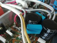
Anyway. I'm having problems finding replacement caps for the 10000uF, 63V. The ones that are fitted are 35mm wide, 75 mm high, 4 "legged" with 22mm spacing of + and -. I've spent hours looking but cant find any new capacitors with the same spec. The limiting factors (besides 10kuF and 63V) are 35mm wide (no place to fit anything wider) and the 22mm spacing.
Anybody know of any capacitor that would fit, or have suggestions on how to solve the problem in any other way would be much appreciated.
//h
I plan (need) to replace a couple of capacitors in a pair of Rotel RB-980BX. Some of the capacitors are starting to look like frozen beer cans after 25 years or something
Anyway. I'm having problems finding replacement caps for the 10000uF, 63V. The ones that are fitted are 35mm wide, 75 mm high, 4 "legged" with 22mm spacing of + and -. I've spent hours looking but cant find any new capacitors with the same spec. The limiting factors (besides 10kuF and 63V) are 35mm wide (no place to fit anything wider) and the 22mm spacing.
Anybody know of any capacitor that would fit, or have suggestions on how to solve the problem in any other way would be much appreciated.
//h
The bigger the better(-:
1 x Panasonic UP 15000uF 63V DC Through Hole Aluminium Electrolytic Capacitor | eBay
1 x Panasonic UP 15000uF 63V DC Through Hole Aluminium Electrolytic Capacitor | eBay
Thank's for help and suggestions. A follow up question would then off course be if there is any potential issues with using bigger capacitors (bigger as in higher capacitance)?
You may put excessive stress on the bridge rectifiers doing this, or cause inrush current issues that make the transformer primary fuse pop or your circuit breaker trip. 10,000uF per rail per channel is already very generous!
No stress;-)
I would build in capacity, that's doable in size. 15 mF or 22 mF;-)
Furthermore I would replace the rectifier-bridges by shottky-diodes.
And I would connect the "mono" -psus. May be per switcher first - to listen the bollock "double-mono"-)
And I would remove the rectifier-bridge-bypass-capacities (10 nF, 500 V?)
Is it possible you could drill a hole in the board so that 10mm spacings could be used? Or perhaps one of the dummy pin holes could be re-used?
Would it be safe to drill new holes? The existing holes are fairly centered on the leading part of the PCB (dont know the exact term, I hope you understand) and new holes would need to be much closer to the edge. The dummy holes are just holes where there is not nothing but fiber glass on the PCB.
Maybe change the rectifiers for 35A types and mount them somewhere to keep them cool.. other than that, no. I dont believe Schottky diodes for mains frequency rectification make any difference in sound quality.
Thought, we were in diyaudio, experienced and loving sound;-)
Just try;-)
No stress;-)
I would build in capacity, that's doable in size. 15 mF or 22 mF;-)
Furthermore I would replace the rectifier-bridges by shottky-diodes.
And I would connect the "mono" -psus. May be per switcher first - to listen the bollock "double-mono"-)
And I would remove the rectifier-bridge-bypass-capacities (10 nF, 500 V?)
Pls bear with me but I don't fully (not at all to be honest) understand the third suggestion, about the '"mono" -psus...'
Would it be safe to drill new holes? The existing holes are fairly centered on the leading part of the PCB (dont know the exact term, I hope you understand) and new holes would need to be much closer to the edge. The dummy holes are just holes where there is not nothing but fiber glass on the PCB.
It should be safe as long as you do not break the PCB drilling them, and theres enough gap between them so that there is no short circuit when you solder in the new parts. You can remove some of the green soldermask from the PCB traces to make new "pads".
Once you have soldered in the new capacitors, I would glue them to the top of the PCB using hot-melt glue, for stability
I don't know if you have access to Digi-Key, but the part below is a drop-in replacement for your amplifier.
Digi-Key Part Number 338-2101-ND
12000µF 63V Aluminum Electrolytic Capacitors Radial, Can - Snap-In - 4 Lead 3000 Hrs @ 85°C
I would not buy large caps on ebay, ever. Your amp has a separate bridge rectifier and filter cap pair for each channel. There is no point to doubling the capacitance since the 10000uF pair designed in is quite enough.
Don't see any point to using Schottky's either, that is if you could find some with high enough breakdown voltage.
Significantly increasing the reservoir cap size beyond the design spec can give the transformer a hard time under higher current draw situations as copper losses start to have increasing effect and magnetic saturation of the core become significant causing the transformer to run hotter.
I recently replaced my psu caps in my Rotel RA-820BX2. I feel your frustration. I ended up moving from 8200uF to 10000uF as I couldn't find the right diameter caps and I seen people doing it before like the similar model. The power is better but turn on power 'thump' is louder.
I also replaced Denon amp from leaded caps to snap-in but used dummy holes next to originals.
I also replaced Denon amp from leaded caps to snap-in but used dummy holes next to originals.
Attachments
"Mono"-psu = channel-separate-psu. Each channel has an (exacter: two;-) own psu. Connect these.
Increasing the psu-capacitance: May be, you will need fatter fuses.-)
The rectifier and the trafo will do their jobs very well.
And test shottky-diodes anytime - and tell us the results;-)
Increasing the psu-capacitance: May be, you will need fatter fuses.-)
The rectifier and the trafo will do their jobs very well.
And test shottky-diodes anytime - and tell us the results;-)
No, you have no evidence that will be the case nor that it will be safe for this particular amp. That's why people who are qualified to say "no" in their advice, do so."Mono"-psu = channel-separate-psu. Each channel has an (exacter: two;-) own psu. Connect these.....Increasing the psu-capacitance: May be, you will need fatter fuses.-)
The rectifier and the trafo will do their jobs very well.....
I have had several customers insist that I fit larger caps in old and sick budget amplifiers to give them a new lease of life but failures weren't expected, were they? One amplifier blew it's power transformer plus the diodes, another just blew the internal transformer fuse. That's only a couple of cases, there were more that were DOA too, until I learned how dumb this practice was with commercial products and how bad it was for reputations.
DIY is a different matter - you can build as much overkill and redundancy into an amp. as will fit inside the case and maybe, if you read the "how to design a power supply" instructions right, it could cope with many times the capacitance. With class A amplification, that will probably be true to an extent.
Some old amps that were designed to suit more than one model, may indeed cope with 2X the specified capacitance but there are plenty of newer models that are built to fine limits and will soon be toast if you overdo smoothing caps. What's more, plenty of the old style class AB amps actually sound fine with only about 4.7 mF per rail. More capacitance may actually sound worse. For example, smaller NAD models once had this type of behaviour.
Thank you all for all helpful information, suggestions and recommendations. Much appreciated.
As for now I’m replacing the caps with slightly larger ones then the ones fitted. From 10000uF to 12000 uF (mainly because I could not find any with the original spec that would physically fit).
I’m saving all the other suggestions as possible, and interesting, future upgrades and modifications.
As for now I’m replacing the caps with slightly larger ones then the ones fitted. From 10000uF to 12000 uF (mainly because I could not find any with the original spec that would physically fit).
I’m saving all the other suggestions as possible, and interesting, future upgrades and modifications.

I have a pair of Rotel 970bx I have been using happily in bridged mode for my OB bass speakers for a while. No problems yet (knock on wood).
I did have the covers off when I was setting them up because I had one channel out.
It appears to have been the switch to set one amp to Bridge/Stereo. Anyway, I got it working by switching it back and forth a few times after spraying some electronics cleaner as best I could into the switch.
I blew them out gently with some compressed air. Didn’t notice any ugly deformed caps, so I put them to work.
While I was trying to figure out why one amp wouldn’t work in bridge mode I came across a thread on here in which some one devoted quite a bit of time and energy to improving a Rotel amp.
Here’s a link if you’re interested...or just for entertainment. I haven’t pursued any of his ideas personally.
Improve a Rotel amp THD by 20dB!
Last edited:
- Status
- This old topic is closed. If you want to reopen this topic, contact a moderator using the "Report Post" button.
- Home
- Amplifiers
- Solid State
- Replacement caps for Rotel RB-980BX