Hi Everyone,
Don't understand the over-current protection scheme on this amp. Q4 needs to be forward biased to switch on once a threshold (measured across R33) has been reached. It all goes pear shaped after R8 (all references are my part numbering), marked B on the attached waveform. ER+ (emitter resistor high side) is what I would expect to see, minus some loss after going through the 1K5. E, the emitter of Q4 is also shown. I know next to nothing about Spice - if you have any suggestions, parameters / settings I've done wrong, please share. Transistor models are not for the original devices, I have listed these in blue text. If anyone can improve on them and re-upload, that would be great")
Interestingly, if D4 is reversed, then the circuit works, even on a real amplifier. Unfortunately it's a bit too sensitive then.
Q1 approximates the protection circuit IC, we want the junction of Q1 and R27 to stay below pin 1 threshold of approx .7v under normal operating conditions.
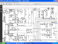
Also attached is a partial of the original 2100 service manual. The full manual is available as a free download from Hi-Fi Engine.
Not related, attached is an image of the waveform as Class-G kicks in, for anyone interested.
Don't understand the over-current protection scheme on this amp. Q4 needs to be forward biased to switch on once a threshold (measured across R33) has been reached. It all goes pear shaped after R8 (all references are my part numbering), marked B on the attached waveform. ER+ (emitter resistor high side) is what I would expect to see, minus some loss after going through the 1K5. E, the emitter of Q4 is also shown. I know next to nothing about Spice - if you have any suggestions, parameters / settings I've done wrong, please share. Transistor models are not for the original devices, I have listed these in blue text. If anyone can improve on them and re-upload, that would be great
Interestingly, if D4 is reversed, then the circuit works, even on a real amplifier. Unfortunately it's a bit too sensitive then.
Q1 approximates the protection circuit IC, we want the junction of Q1 and R27 to stay below pin 1 threshold of approx .7v under normal operating conditions.
Also attached is a partial of the original 2100 service manual. The full manual is available as a free download from Hi-Fi Engine.
Not related, attached is an image of the waveform as Class-G kicks in, for anyone interested.
Attachments
Forgot to add the .asc file will want to access a txt file in c:\ for some of the models. I used a zip file posted by Mooly in 2018. I see the file contains Cordel models and is copyrighted so didn't attach it. I'm sure there will be an updated version by now available for download on diyaudio.
- Status
- This old topic is closed. If you want to reopen this topic, contact a moderator using the "Report Post" button.