Hi
I will get a Classe Twenty five I will refurbish with new caps. As this amp has an input cap which is not needed, I will bypass it. My preamp can be used in balanced mode si I will try it with the Classe. If I bypass C1 in standard use, can I also bypass c9 for balanced mode ?
Thanks
I will get a Classe Twenty five I will refurbish with new caps. As this amp has an input cap which is not needed, I will bypass it. My preamp can be used in balanced mode si I will try it with the Classe. If I bypass C1 in standard use, can I also bypass c9 for balanced mode ?
Thanks
Attachments
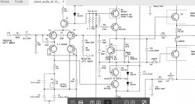
The input circuit is a little odd.
No leakage resistor to discharge the input cap, no RF suppression cap. Somewhat large resistance values in the feedback and input network, if noise is an issue that's probably why.
DC coupling is perfectly feasible as the feedback network gives unity DC gain, but if you are worried about C1, you'd also worry about C9? You might worry why C1 and C9 have different values.
Last edited:
Why do you say these caps are not necessary?
As there's 0 volts at Q2 base, why using a cap there if the preamp doesn't have any DC offset ? Best cap is no cap at all if not needed.
Now how about C9 ?
Its a differential stage with matching networks, the imbalance cannot be more than a few tens of mV as it consists of the Vbe mismatch of Q2/Q3.
One argument against DC coupling is if the source isn't well behaved, it could either trigger the power amp protection circuitry or cook the speakers. This is why AC coupling is nearly always used in commercial amps, to avoid getting a bad reputation for failures that may not be your fault.
One argument against DC coupling is if the source isn't well behaved, it could either trigger the power amp protection circuitry or cook the speakers. This is why AC coupling is nearly always used in commercial amps, to avoid getting a bad reputation for failures that may not be your fault.
Last edited:
Actually thinking about it the DC coupled version is going to have loud clicks on plugging in due to the large resistance values in the networks - 113k is going to drop quite a voltage taking the base current, until a DC source is plugged in and bringing the 3k83 in paralllel to it...
Cap was bypassed and this gave an amazing difference. It was done only for single mode operation not balanced mode.
FYI: This amp sounds far better driven single-ended as the IC based balancing stage is pretty rudimentary.
Hi
I will get a Classe Twenty five I will refurbish with new caps. As this amp has an input cap which is not needed, I will bypass it. My preamp can be used in balanced mode si I will try it with the Classe. If I bypass C1 in standard use, can I also bypass c9 for balanced mode ?
Thanks
You mention that the input cap. is not needed. While the schematic you posted doesn't show the ouput stage, I feel 99% certain there is no DC servo. Which means that, as others in this thread have pointed out, that 100uF C9 reduces overall gain to unity at DC, which means it will not amplify DC. However, it would pass any DC at the input to the output if it weren't for input cap. C1. Removing C1 would be risky for your speakers.
If you want to experiment with the C1 and C9, I suggest swapping them with some other type caps. Of at least the same voltage and capacitance, but do not operate you amp with either of those caps. removed from the circuit.
A few millivolts difference between Q2 and Q3 will be amplified with open loop gain, only to be adjusted with the feedback loop on the imbalanced differential stage of Q2 and Q3.
This yields into overall inbalance throughout the circuit, to have this same amount of millivolts on the output terminal.
This yields into overall inbalance throughout the circuit, to have this same amount of millivolts on the output terminal.
Hi
I will get a Classe Twenty five I will refurbish with new caps. As this amp has an input cap which is not needed, I will bypass it. My preamp can be used in balanced mode si I will try it with the Classe. If I bypass C1 in standard use, can I also bypass c9 for balanced mode ?
Thanks
Please do, your speakers will love it.
Less caps means better sound.

It's awfully risky to eliminate those capacitors, especially C9. If you eliminate C9, then the amplifier will have full gain at DC. I predict disaster.
The pole created by C9 and R5? (I can't see it) should be lower than the input pole; ideally by a factor of ten. Haphazard stacking of poles can contribute to capacitors impinging on the sound. When the circuit is designed properly, the capacitors will have absolutely zero effect on the sound.
The pole created by C9 and R5? (I can't see it) should be lower than the input pole; ideally by a factor of ten. Haphazard stacking of poles can contribute to capacitors impinging on the sound. When the circuit is designed properly, the capacitors will have absolutely zero effect on the sound.
Please do, your speakers will love it.
Less caps means better sound.
This amplifier is a balanced input configuarion (as used in pro equipment).
This is given by R1-R2 and R8-R15.
C5 is 5u in combination with R2 (113k): Fo= 0.28 Hz
C9 is 100u icw R8 (3k83): Fo=0.42 Hz
If you bypass the caps, you will create a perfect instable amplifier, if not a shortwave transmitter @ random frequency.
Keep the patches and icecubes at hand.
This is given by R1-R2 and R8-R15.
C5 is 5u in combination with R2 (113k): Fo= 0.28 Hz
C9 is 100u icw R8 (3k83): Fo=0.42 Hz
If you bypass the caps, you will create a perfect instable amplifier, if not a shortwave transmitter @ random frequency.
Keep the patches and icecubes at hand.
- Status
- This old topic is closed. If you want to reopen this topic, contact a moderator using the "Report Post" button.
- Home
- Amplifiers
- Solid State
- Classe twenty five DC coupling