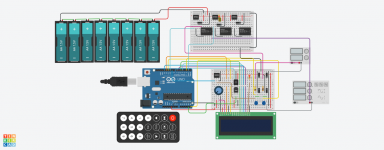
Well here is the teaser to the up coming project feel free to contribute
Code:
/*
Harrison Audio Labs
This is a test bed to simulate soft start , over temp and DC detection, as the project grow bigger, a GPU is necessary as rendering is slow
on client side if GPU not present. This is via tinkercad.com hopefully tinkercad.com will in future provide server side rendering via
GPU arrays with client side ajax calls or other. Only AC detection, DC detection and soft start are included. AC loss and resumption can be tested via provided remotes power button

On loss of AC
Turn speakers off

On resumption of AC
Bypass Thermister after 100ms
Turn speakers on after two seconds on resumption of AC

On Detection of DC
Power off speakers
Power off AC to amp

On over temp
Power off speakers
Power off AC to amp

On fan threshold
power on/off fan

On overcurrent*
It is easy to overcompensate or under compensate,
but manufacturer output devices SOA charts are the starting point
*/

// include library code:
#include <LiquidCrystal.h>
#include <IRremote.h>

unsigned long timeON = 0;
unsigned long timeLOOP = 0;
unsigned long ticks = 0;
float ac_max = 0,ac_min = 0;
bool toggleON = 0;
bool toggleTOROID = 0;
int sensorVal = 0;
int sensorValMax = 0, sensorValMin = 0;
float dvd = 10.0/3.0;
bool ac_ready =0;
int dc = 0;
int ac_dc = 0;
int dc_time = 0;

//IR sensor pin
const int RECV_PIN = 7 ;
const int sensorPin = A0; //temperature
const int apin10 = PB2;
const int acPin = A5;
const int dc_pin = PD2;
const int dc_reset = PB1;
const int acLED = PD1;
// Define IR Receiver and Results Objects
IRrecv irrecv(RECV_PIN);
decode_results results;
// initialize the library with the numbers of the interface pins
LiquidCrystal lcd(12, 11, 5, 4, 13, 6);
//Counter and compare values
const int t1_load = 0;
const uint16_t t1_comp = 600;

void setup() {

  DDRB |= (1 << apin10);
  DDRB |= (1 << dc_reset);
  PORTB |= (1 << dc_reset);

  //reset timer 1 control register a
  TCCR1A = 0;
  //set to prescalar 8
  TCCR1B &= ~(1 << CS12);
  TCCR1B |= (1 << CS11);
  TCCR1B &= ~(1 << CS10);
  //reset and compare timer
  TCNT1 = t1_load;
  OCR1A = t1_comp;
  //enable t1 compare interrupt
  TIMSK1 = (1 << OCIE1A);
  //enable global interrupts
  sei();
  // Enable the IR Receiver
  irrecv.enableIRIn();
  // set up the LCD's number of columns and rows:
   lcd.begin(16, 2);
}

void loop() {
  int sensorVal = analogRead(sensorPin);
  //convert the ADC reading to voltage
  float voltage = (sensorVal/1024.0)*5.0;
  float temperature = (voltage - .5)*100;

  ac_max = (sensorValMax/1023.0) * 5.0;
  ac_min = (sensorValMin/1023.0) * 5.0;

  //Detect AC
  if ((ac_ready == 0) && (timeLOOP-timeON >= 20) && ((ac_max + ac_min) < 1) && (ac_max > 1))
  {
    lcd.setCursor(0, 0);
    lcd.print(String("Power On: ") + String(timeLOOP-timeON) + String("ms"));
     ac_ready = 1;
  }

  //Detect sudden power loss
  if (ac_ready == 1 && !( ((ac_max + ac_min) < 1) && (ac_max > 1) ) && (timeLOOP-timeON >= 200)){
      ac_ready = 0;
        dc_time = 0;
        dc = 0;
        toggleTOROID = 0;
        PORTD &= ~(1 << acLED);
  }
  //Slow start toroidal
  if (ac_ready == 1 && (timeLOOP-timeON >= 200) && toggleTOROID == 0){
      toggleTOROID = 1;
      PORTD |= (1 << acLED);
  }
  //Presence of DC
  if(dc == 1 && dc_time == 0 && ac_ready == 1 ) {

    lcd.setCursor(0, 1);
    lcd.print(String("Fault DC: ") + String(int(ticks/dvd)) + String("ms"));
    dc_time ++;
  }
  //Fetch remote control codes and toggle power on and off
  if (irrecv.decode(&results)){
    switch(results.value){
          case 0xFD00FF: //Red Keypad Button
            if(toggleON==0){
                PORTB &= ~(1 << dc_reset);
                 PORTB |= (1 << apin10);
            toggleON=1;
                ticks = 0;
                timeON = millis();
             }
              else {
                PORTB &= ~(1 << apin10);
                PORTB |= (1 << dc_reset);
                toggleON=0;
            }
             break;
    }
    irrecv.resume();
  }
  timeLOOP = millis();
  if(toggleON==0 && timeON == 0){
    lcd.setCursor(0, 0);
    lcd.print("OFF");
    }
  if(toggleON==0 && timeON > 0){
    lcd.clear();
    timeON = 0;

  }

}
//Our DC sensor ISR
ISR(TIMER1_COMPA_vect){
   TCNT1 = t1_load;
  dc = (PIND & (1 << dc_pin)) >> dc_pin;

  sensorVal = analogRead(acPin);

  if(sensorValMax < sensorVal){
    sensorValMax = sensorVal;
  }

  if(sensorValMin > sensorVal){
    sensorValMin = sensorVal;
  }

  ticks++;
}
Attachments
A nano is only £2 & a pro mini £1.30 from China so cheap enough.
Great if you are not into PCB manufacture.
Great if you are not into PCB manufacture.
A Raspberry Pi would be a sledgehammer. An Arduino is cheap with a decentArduino ? whats wrong with a 70p 8 pin PIC12F509 ?
Sledge hammer to crack a nut !
IDE and a large library covering a lot of avenues.
BTW I use Arduino to control my 5.1 homebrew system so I admit I'm biased.
G²
I cannot recognize the parts you are using in your Fritzing.
Nevertheless, I think you don't need battery buffers. All you need is a fast enough AC loss detection. E.g. you could use an ABLIC S-80842CNY (have a look at the datasheet and its typical applications). As the amplifiers' supplies are typically packed with tons of big capacitors, it's easy too design a detection crcuit which is way faster by directly accessing the transformer outputs of your 5V supply 😉
For efficient inrush limiting you might have a look here:
Elektor 5/2006
(s. page 72, I prefer to use antiserial Zeners). But, of course, if you have an Arduino in place 😉
The advantage of the Arduinos (besides the price) is that they have a bootloader and the compiler doesn't loose the optimizations after a couple of weeks 😉Arduino ? whats wrong with a 70p 8 pin PIC12F509 ?
Sledge hammer to crack a nut !
An Arduino is a good dev board for doing things with Atmel AVR's in general. The Arduino IDE and libs can be a good starter kit for introducing one to programming microcontrollers.
It's a short step from there to using the compiler directly (it's just gcc underneath) and directly programming the AVR hardware rather than using the libraries. From there you can move up to using an IDE like code::blocks and other AVR chips. They are an excellent "starter kit" for working with microcontrollers in general, and they are really cheap 🙂
It's a short step from there to using the compiler directly (it's just gcc underneath) and directly programming the AVR hardware rather than using the libraries. From there you can move up to using an IDE like code::blocks and other AVR chips. They are an excellent "starter kit" for working with microcontrollers in general, and they are really cheap 🙂
I had the benefit of coming from a PIC consultancy for 13 years.
We used to just choose the cheapest PIC that will do the job.
Most of our projects were very tight on budget.
After that the skys the limit.
I am currently working on a PIC32MZ running at 200MHZ for a USB scope.
Writing PIC code in assembly isn't the friendliest thing.
But the 4MHZ micros all run at 1uS per instruction which is great for timing loops.
With PIC's the datasheet is vital for setting up things like timer's PWM, A2D etc etc
I just spent an hour trying to get a PWM to work then realised I was accessing register in wrong memory bank !
Great care is needed with PIC code so not for the faint of heart.
While PIC programming will put hairs on your chest, it will probably lose a few from the top of your head from head scratching.
Last edited:

Thats the main reason I preferred AVR. The instruction set is far better, and the existence of the GCC toolchain for it means it's much easier to use, especially so if you are already familiar with the GCC toolchain from Linux or Mac, as I am. Sure there are C compilers for PIC's, but they are custom jobs with catches, and expensive.
Well here is the teaser to the up coming project feel free to contribute
Code:/* Harrison Audio Labs This is a test bed to simulate soft start , over temp and DC detection, as the project grow bigger, a GPU is necessary as rendering is slow on client side if GPU not present. This is via tinkercad.com hopefully tinkercad.com will in future provide server side rendering via GPU arrays with client side ajax calls or other. Only AC detection, DC detection and soft start are included. AC loss and resumption can be tested via provided remotes power button On loss of AC Turn speakers off On resumption of AC Bypass Thermister after 100ms Turn speakers on after two seconds on resumption of AC On Detection of DC Power off speakers Power off AC to amp On over temp Power off speakers Power off AC to amp On fan threshold power on/off fan On overcurrent* It is easy to overcompensate or under compensate, but manufacturer output devices SOA charts are the starting point */ // include library code: #include <LiquidCrystal.h> #include <IRremote.h> unsigned long timeON = 0; unsigned long timeLOOP = 0; unsigned long ticks = 0; float ac_max = 0,ac_min = 0; bool toggleON = 0; bool toggleTOROID = 0; int sensorVal = 0; int sensorValMax = 0, sensorValMin = 0; float dvd = 10.0/3.0; bool ac_ready =0; int dc = 0; int ac_dc = 0; int dc_time = 0; //IR sensor pin const int RECV_PIN = 7 ; const int sensorPin = A0; //temperature const int apin10 = PB2; const int acPin = A5; const int dc_pin = PD2; const int dc_reset = PB1; const int acLED = PD1; // Define IR Receiver and Results Objects IRrecv irrecv(RECV_PIN); decode_results results; // initialize the library with the numbers of the interface pins LiquidCrystal lcd(12, 11, 5, 4, 13, 6); //Counter and compare values const int t1_load = 0; const uint16_t t1_comp = 600; void setup() { DDRB |= (1 << apin10); DDRB |= (1 << dc_reset); PORTB |= (1 << dc_reset); //reset timer 1 control register a TCCR1A = 0; //set to prescalar 8 TCCR1B &= ~(1 << CS12); TCCR1B |= (1 << CS11); TCCR1B &= ~(1 << CS10); //reset and compare timer TCNT1 = t1_load; OCR1A = t1_comp; //enable t1 compare interrupt TIMSK1 = (1 << OCIE1A); //enable global interrupts sei(); // Enable the IR Receiver irrecv.enableIRIn(); // set up the LCD's number of columns and rows: lcd.begin(16, 2); } void loop() { int sensorVal = analogRead(sensorPin); //convert the ADC reading to voltage float voltage = (sensorVal/1024.0)*5.0; float temperature = (voltage - .5)*100; ac_max = (sensorValMax/1023.0) * 5.0; ac_min = (sensorValMin/1023.0) * 5.0; //Detect AC if ((ac_ready == 0) && (timeLOOP-timeON >= 20) && ((ac_max + ac_min) < 1) && (ac_max > 1)) { lcd.setCursor(0, 0); lcd.print(String("Power On: ") + String(timeLOOP-timeON) + String("ms")); ac_ready = 1; } //Detect sudden power loss if (ac_ready == 1 && !( ((ac_max + ac_min) < 1) && (ac_max > 1) ) && (timeLOOP-timeON >= 200)){ ac_ready = 0; dc_time = 0; dc = 0; toggleTOROID = 0; PORTD &= ~(1 << acLED); } //Slow start toroidal if (ac_ready == 1 && (timeLOOP-timeON >= 200) && toggleTOROID == 0){ toggleTOROID = 1; PORTD |= (1 << acLED); } //Presence of DC if(dc == 1 && dc_time == 0 && ac_ready == 1 ) { lcd.setCursor(0, 1); lcd.print(String("Fault DC: ") + String(int(ticks/dvd)) + String("ms")); dc_time ++; } //Fetch remote control codes and toggle power on and off if (irrecv.decode(&results)){ switch(results.value){ case 0xFD00FF: //Red Keypad Button if(toggleON==0){ PORTB &= ~(1 << dc_reset); PORTB |= (1 << apin10); toggleON=1; ticks = 0; timeON = millis(); } else { PORTB &= ~(1 << apin10); PORTB |= (1 << dc_reset); toggleON=0; } break; } irrecv.resume(); } timeLOOP = millis(); if(toggleON==0 && timeON == 0){ lcd.setCursor(0, 0); lcd.print("OFF"); } if(toggleON==0 && timeON > 0){ lcd.clear(); timeON = 0; } } //Our DC sensor ISR ISR(TIMER1_COMPA_vect){ TCNT1 = t1_load; dc = (PIND & (1 << dc_pin)) >> dc_pin; sensorVal = analogRead(acPin); if(sensorValMax < sensorVal){ sensorValMax = sensorVal; } if(sensorValMin > sensorVal){ sensorValMin = sensorVal; } ticks++; }
The devil is always in the details. Your 8 cells will last an 'eternity' powering an Arduino. In reality you need only a few seconds. If your relays are active when energized, power loss 'processing' is nearly automatic. Detecting power loss with the processor could easily detect a missing half cycle of the AC line but does it need to be that sensitive? Temperature detection is minor but again, why is it under designed that that is a problem? I've only been playing with DC coupled solid state amps for 50 years and worked as a consumer audio repair tech and in broadcast TV for 40 + years and have never run into a DC amp that wrecked a speaker from DC on the output. Another question is how long do you wait to call it a fault? I was checking some LOW frequencies for testing an amp and was using a 2 Hz square wave just to check the rolloff from the coupling caps. The AC coupling on my Rigol scope is about 5 times worse than the PC output and the Niles Audio DA I use.
ISTM you're trying to make it 'smart' to mask engineering shortcomings.
Sorry to be so harsh.
G²
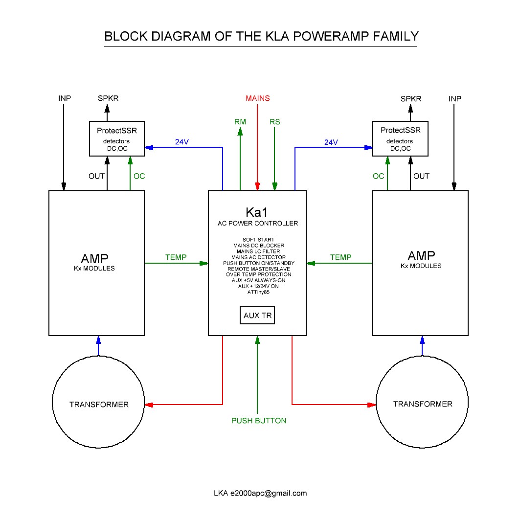
I recommend you to divide the protection (DC,OC) and controlling functions.
control : MCU based (arduino nano, attiny84/85), soft start, on/off, temperature, fan, etc
protection : SSR on "analog" base (no MCU), shortest path, far away from transformers/mcus
Check this out.
control : MCU based (arduino nano, attiny84/85), soft start, on/off, temperature, fan, etc
protection : SSR on "analog" base (no MCU), shortest path, far away from transformers/mcus
Check this out.
Attachments
Last edited:
Getting into PICs is a nightmare, I gave up, just too complicated (at least a dozen instruction sets I think), you could spend literally days deciding which was the best device for a particular application (only worth it for high volume, not useful to DIY tinkering at all). Luckily I came back to electronics and microcontrollers when the Arduino appeared, easy to use, no faff, and open-source/multi-platform, so no vendor lock-in, and architecture neutral software model - basically put together with some understanding of how an eco-system works, which is why its so successful - general/simple/extensible/open/examples
Here's one I prepared earlier, and have had operating on my amplifier for a few years now GitHub - phenidone/fancontrol: Smart PID fan controller for audio amplifiers.
It doesn't do speaker protection, but it is a fan controller with overtemp protection and remote control. Feel free to make use of the source, or I have a few spare (assembled, programmed and tested boards) here that I was intending to sell on tindie but never got around to it.
It doesn't do speaker protection, but it is a fan controller with overtemp protection and remote control. Feel free to make use of the source, or I have a few spare (assembled, programmed and tested boards) here that I was intending to sell on tindie but never got around to it.
If you need some "inspiration", you might want to check professional designs of the detection circuits, as well. For example, you could have a look at the HK3490 service manual on this page.
On page 107 you see the schematic of the main pcb which has OC, DC and overtemp detection, all cumulated on the PROTECT_L port
Additionally, there is an AC loss detection on POWER_D.
Both are designed to be evaluated by an MCU which, in turn, controls SPK1 and SPK2.
Hint1:
AC loss is not only used to turn off the speakers, but also to store values to NVM like sound settings before powering off the MCU.
Hint2:
I like LKA's SSRs 😉
Last edited:
Hello All,
I'm pleased to see the new thread on microcontroller-based amp control board
If you are interested in my experience - here is the thread I have started in 2014 on the AVR-based control boards:
How to build a 21st century protection board
The initial design is rather immature, however, it still works perfectly on my test bench.
Here is the page with very mature design V6.0 having opto-isolated grounds for dual-mono amp configurations:
Control Board V6.0
We use hardware interrupts, hardware acceleration, SS relays, controlled PSU rails, etc., utilizing the modular structure (Control module, Speaker relays module, Power relays module).
You can see some of our latest developments following the link in my signature as well.
If you have questions - please feel free to contact me or jwilhelm 😉
Cheers,
Valery
A wealth of information. A collection of seasoned engineers some from some leading brands. Cheers again.
Thanks Nigel C is as close as possible as one can get to assembly without hairloss. It has faster development times, some automation and easy to write tests. You see even this small program has bugs. Most software bugs go unnoticed for millenia and others will remain unnoticed. However seasoned designers like you prefer the PIC family, some even use logic gates and flip flops.
Engineers who worked on analog computers back in the day may find that analog might be the way to go.
PIC, ATtiny et al is all good but arduino comes with more pinsand as Stratus46 and Mark pointed out, dozens of libraries for doing all sorts of things.
Fvzeppelin, thanks for the Elektor creative ideas and also the HK3490 had a listen to it way back in a show room but it wasn’t burned in yet, cant remember what JBL speakers they were using and whether the sources were high res or not so it wouldn’t be fair to say the good or bad about it plus there were other interfering sound sources
Yes Nigel speed is an issue in some applications, however on a light note you could go bigger and use a Raspberry with non optimized Python or Java code 🙂
Thanks LKA, Valery and Laplace for more great ideas. Will dig into your designs in the coming weeks and see what we can brew.
By the way who spotted the bugs in the diagram and the code 😀
Yes, and this makes prototyping fast and easy 🙂 And when you're done (if this should ever be the case in a diy project), you can still easily burn your sketch on an Attiny (and maybe also get rid of the bootloader in this step) 😀PIC, ATtiny et al is all good but arduino comes with more pinsand as Stratus46 and Mark pointed out, dozens of libraries for doing all sorts of things.
I ripped the whole DSP/preamp section out of mine and now I'm very happy with it:Fvzeppelin, thanks for the Elektor creative ideas and also the HK3490 had a listen to it way back in a show room but it wasn’t burned in yet, cant remember what JBL speakers they were using and whether the sources were high res or not so it wouldn’t be fair to say the good or bad about it plus there were other interfering sound sources
HK3490 mod
That's why I know the schematics a little bit better than usual...
As you were talking about libraries: You might want to check out this library. It offers fastDigitalIO functions which could be used to replace your direct register accesses. Makes code a lot more readable and less prone to bugs...By the way who spotted the bugs in the diagram and the code 😀
Cheers 😉
- Status
- Not open for further replies.
- Home
- Amplifiers
- Solid State
- Arduino Amplifier Control and Protection