Hi all,
A long time ago I repaired/slightly upgraded a QUAD-405. One of the broken down components was the electrolytic capacitor in the DC feedback loop. Instead of replacing it, I modified the DC bias loop such that it had nearly the same response with a much smaller capacitor and replaced the electrolytic capacitor with a film capacitor (metallized MKT, to stay in style with the rest of the amplifier). I also reduced the sensitivity so it needs about 0.75 V rather than 0.5 V.
I wrote down my calculations in an ASCII file (going a bit overboard, as usual) and then lost the file, but to my surprise, I just found a back-up I didn't know I had. I'll attach it to this message just in case anyone else wants to modify a QUAD-405 DC bias loop.
The one and only combination I have tried in real life is:
C1 = 680 nF
R3 = 22.1 kohm
R6 = 221 kohm
C4 = 68 nF
R4 = 68 kohm
R5 = 56 kohm
C2 = 2.2 uF.
Mind you, if the cut-off frequency of the bias loop is lowered very much and the signal contains strong deep subsonics, the DC protection may trigger. If the SOAR protection is disabled or if the modules are not properly mounted on the heatsink, this may destroy the output transistors and DC protection TRIACs. In order to prevent false triggering of the DC protection, do not make the cut-off frequency lower than a couple of Hz or adjust the DC protection time constant.
Best regards,
Marcel
Edit: the simulations of post #5 don't look the way they are supposed to, but that's due to a discrepancy in the value for R16, as becomes apparent further in the thread.
Attachments
Last edited:
Several reasons:
-The original DC feedback capacitor that had failed was actually a tantalum electrolytic capacitor. Nowadays (since the Americans passed the Dodd-Frank act) you can buy tantalum capacitors that are guaranteed to be conflict-mineral free, but back then it was anybody's guess whether the tantalum came from a legitimate source or from Rwandan military plundering Congolese mines. Hence, I certainly didn't want to replace it with a new tantalum cap.
-There were more problems with the amplifier I repaired than just the DC feedback capacitor. I wanted a capacitor with enough voltage handling in either direction to ensure that it would not fail again if there should be a large DC voltage at the output due to some other failure.
-Besides, the redesign reduces the noise floor of the amplifier somewhat and reduces capacitor distortion.
Reducing the gain definitely does, these were far too sensitive at 500mV although I understand it was the "norm" in those days ... I modded mine for 1.25v as well as adding local mlcc decoupling on the opamps (they were already NE553x but there was no local decoupling). This made for a noticeable reduction in the noise floor.
Mine's not the "real deal" sadly, but it is an "exact copy" minus the protection daughterboard built sometime in the early 80's.
Anyway an interesting read, and thanks for the detailed reasoning. I'm tempted to try flipping the opamp (to non inverting mode) at some point but since it's a more complicated mod and the benefits are dubious, I will probably hold off until I need to overhaul for other reasons.
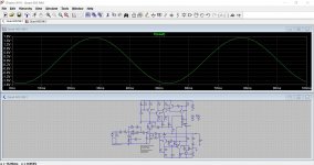
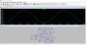
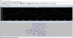
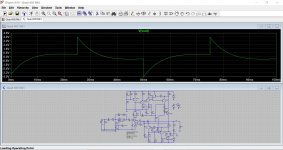
This shows the effect of the mods in post #1 on the overall response and on how it handles a squarewave at 20Hz and also a sine at 20Hz.
The modded version is the second image in each group.
Edit... I have added the .asc file for anyone wanting to play although you will have to use your own models (or default library ones).
The modded version is the second image in each group.
Edit... I have added the .asc file for anyone wanting to play although you will have to use your own models (or default library ones).
Attachments
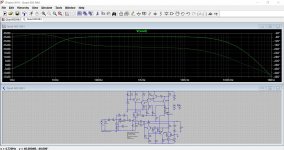
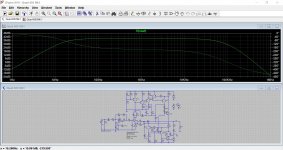
They look almost no different... Am I missing something?This shows the effect of the mods in post #1 on the overall response and on how it handles a squarewave at 20Hz and also a sine at 20Hz.
The modded version is the second image in each group.
Edit... I have added the .asc file for anyone wanting to play although you will have to use your own models (or default library ones).
[emoji23] duh!Third sentence of the first post: "I modified the DC bias loop such that it had nearly the same response with a much smaller capacitor".
This shows the effect of the mods in post #1 on the overall response and on how it handles a squarewave at 20Hz and also a sine at 20Hz.
The modded version is the second image in each group.
Edit... I have added the .asc file for anyone wanting to play although you will have to use your own models (or default library ones).
Hi Mooly,
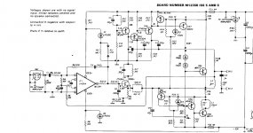
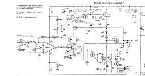
I just looked at your .asc file, compared the schematic with the QUAD-405 schematics I know and found some discrepancies.
Resistor R16 is 100 ohm in your model, but 180 ohm in the schematics I have seen and used for my calculations. This may explain why the bass rolls of so much in your simulations.
Resistors R4 and R5 are 10 kohm each in your model, but 22 kohm and 4.7 kohm in the schematics I have (although I vaguely remember having seen two times 10 kohm before). This shouldn't make much of a difference for the roll-off, though.
Thanks for spotting that Marcel. I probably used the original service manual diagrams to create the .asc and there were so many variations. It does look like the 10k + 10k version should indeed go with 180 ohm for R16 and the 22k and 4k7 went with 100 ohm.
Well spotted")
If you have the original Quad manual as a pdf and load it into Adobe Reader you can click through the pages and see each schematic image change like an old flick book animation and without the images shifting on the screen.
Well spotted
If you have the original Quad manual as a pdf and load it into Adobe Reader you can click through the pages and see each schematic image change like an old flick book animation and without the images shifting on the screen.
Hello Marcel and others.
I had your original document about the loops for a long time, I tried the values in the original document, but it is a pity you lost the 12dB slope. It is strange, at least to me, why the 12dB slope is dependent on the value of the components. A second maybe trivial question is why in the original circuit the time constant of R5 and C2 has to be multiplied by the overall closed loop gain to get the effective value (see the explanation of Keith Snook on his website). Sorry for the questions and no contribution.
Joost Plugge
Hello Marcel,
In the original setup the slope of the input filter is 12dB/Oct, after changing the values, the slope is 6dB, but you explained this in your paper. I was looking for values of the components that will lower the value of C2 without loosing the 12dB slope of the input filter. But I asume that is not possible.
Joost
- Status
- This old topic is closed. If you want to reopen this topic, contact a moderator using the "Report Post" button.
- Home
- Amplifiers
- Solid State
- Redesigning QUAD-405 DC bias loops