Hi all; I have my Dad's old Aurex SB-66 integrated amp built by Toshiba. Do any of you have the exact model? I am blowing the main fuse on the AC input; 5 Amp, 250 Volt. I suspect I may have fried one or more output transistors. Have any of you had this problem with this amplifier? I think I'll order all new output AND driver transistors just to be sure; I think replacements are all still available at just a few bucks a piece? There is one very long finned aluminum heatsink; I haven't looked closely yet; I wonder if I can get the transistors out by themselves or do I need to remove the entire heatsink assembly? Anybody already been down this road on this model? I'm hoping for a few tips and short-cuts here! The first thing I will attempt is to unsolder all driver and output transistors (removing them from the circuit) then see if the fuse still blows. (If it does; that means I'll have to do some honest troubleshooting instead of the quick and dirty just replacing the most suspect parts; something I'd like to avoid if possible!)
file:///C:/Users/Danlt123/Downloads/Toshiba-SB-66-Schematic%20(1).pdf
file:///C:/Users/Danlt123/Downloads/hfe_toshiba_sb-66_schematics.pdf
2 different schematics I found online; not sure if they will open or not
Thanks!
file:///C:/Users/Danlt123/Downloads/Toshiba-SB-66-Schematic%20(1).pdf
file:///C:/Users/Danlt123/Downloads/hfe_toshiba_sb-66_schematics.pdf
2 different schematics I found online; not sure if they will open or not
Thanks!
Hi all; I have my Dad's old Aurex SB-66 integrated amp built by Toshiba. Do any of you have the exact model? I am blowing the main fuse on the AC input; 5 Amp, 250 Volt. I suspect I may have fried one or more output transistors. Have any of you had this problem with this amplifier? I think I'll order all new output AND driver transistors just to be sure; I think replacements are all still available at just a few bucks a piece? There is one very long finned aluminum heatsink; I haven't looked closely yet; I wonder if I can get the transistors out by themselves or do I need to remove the entire heatsink assembly? Anybody already been down this road on this model? I'm hoping for a few tips and short-cuts here! The first thing I will attempt is to unsolder all driver and output transistors (removing them from the circuit) then see if the fuse still blows. (If it does; that means I'll have to do some honest troubleshooting instead of the quick and dirty just replacing the most suspect parts; something I'd like to avoid if possible!)
file:///C:/Users/Danlt123/Downloads/Toshiba-SB-66-Schematic%20(1).pdf
file:///C:/Users/Danlt123/Downloads/hfe_toshiba_sb-66_schematics.pdf
2 different schematics I found online; not sure if they will open or not
Thanks!
well, I'm too tired to fight it tonight; tomorrow I'll try to get the links to work; after I logged out and back in again; they didn't open! Like I said; too tired to fight it right now!
Yeah, we can't open a file on your hard drive. Is this it? Toshiba SB-66 - Manual - Stereo Integrated Amplifier - HiFi Engine.
I see a 2.0 Amp main fuse, not 5A. Start out by using your trusty ohmmeter and check for shorted output transistors.
I see a 2.0 Amp main fuse, not 5A. Start out by using your trusty ohmmeter and check for shorted output transistors.
Yeah, we can't open a file on your hard drive. Is this it? Toshiba SB-66 - Manual - Stereo Integrated Amplifier - HiFi Engine.
I see a 2.0 Amp main fuse, not 5A. Start out by using your trusty ohmmeter and check for shorted output transistors.
Yeah, I realize I tried to copy and paste from my machine, not the actual website. Yep, that's the correct amp. It is definitely a 5 Amp fuse; the marking on the circuit board fuse holder say 5 Amp and the fuse also said 5 A. You still have to unsolder the transistors to read them with an Ohm-meter; measuring them in -circuit won't work. I think my new DMM has the P-N junction test that reads the actual Si or Ge voltage drop when testing diodes and transistors. It also has hFE test I just noticed. My thinking is that even if I only blew one or two devices; they could have all been overly stressed; including the drivers. Oh, I get it! 2 Amp is for 230 Volt mains; 5 Amp is for 115 Volt mains (actually; I have a Japanese market only model not USA or international so it says 100 Volt input). (I got this from a street vendor in Tokyo in the 80's; it has always worked just fine in the US on 115-120 Volts so that has never been an issue).
I'll see if I can get the schematic up I saw the other day. Thanks for the inputs and good catch on that fuse value!!!
OK, I found the outputs on one channel only shorted but am ordering all 4 output transistors anyway. I would order all 4 drivers also but they are much harder to come by. I took all 8 transistors out of the circuit to test them. (The correct service manual/schematic has the correct link someone did for me already so no reason for me to repeat it...thanks for that!).
Newark has the NTE substitute/replacement brands; I also got new mica insulators with new nylon bushings and heat sink compound. I'm glad I don't have to do this for a living anymore! I did stereo repair in HS and college both; that was OVER 40 years ago; my eyesight and eye/hand coordination aren't nearly as good as they used to be. Getting the new outputs in will be tricky; it was tricky getting the old ones out. Luckily; I had a stubby no. 2 Philips screwdriver that I could just barely squeeze into the space. Getting the entire heatsink assembly out would be a minor nightmare! Thanks for the inputs and help; hope this is all there is and not another hidden or latent failure that pops up later!
Newark has the NTE substitute/replacement brands; I also got new mica insulators with new nylon bushings and heat sink compound. I'm glad I don't have to do this for a living anymore! I did stereo repair in HS and college both; that was OVER 40 years ago; my eyesight and eye/hand coordination aren't nearly as good as they used to be. Getting the new outputs in will be tricky; it was tricky getting the old ones out. Luckily; I had a stubby no. 2 Philips screwdriver that I could just barely squeeze into the space. Getting the entire heatsink assembly out would be a minor nightmare! Thanks for the inputs and help; hope this is all there is and not another hidden or latent failure that pops up later!
Remember to use the bulb when testing... it saves any tears at bedtime ")
I haven't looked at the circuit but if its like most amps then there will be some low value resistors connected to those output transistors, typically 0.5 ohm or lower. Check they haven't gone open or gone high in value.
Also set the bias trimmer to the position that gives minimum bias current before powerering on.
I think my problem was accumulated heat. I have ordered some wire rack type shelving so I get much better ventilation. The speakers are very close to 8 Ohms and I didn't really have the amplifier turned up that loud; probably only 35 Watt peaks I'm guessing. So; low impedance not the problem (this amp is NOT rated for 4 Ohms!).
The power supply main rails are now reading + 70 and - 70 VDC without the 4 output transistors installed. Nothing looked burned or charred and I couldn't smell anything that indicated it had gotten hot. Hope the heat was the ONLY real problem here; I'll give the results after my parts get here.
The power supply main rails are now reading + 70 and - 70 VDC without the 4 output transistors installed. Nothing looked burned or charred and I couldn't smell anything that indicated it had gotten hot. Hope the heat was the ONLY real problem here; I'll give the results after my parts get here.
Sometimes parts just fail. Like all of us, they reach end of life and something fails.
I think you may have a higher powered version of the SB-66. The schematic on HFE shows a 2 amp fuse and 50 volt rails. You indicate your unit has a 5 amp fuse and 70 volt rails.
You might want to double check the part number on those output transistors to be sure you are getting appropriate replacement parts. Wouldn't accept what is shown on the schematic.
Last edited:
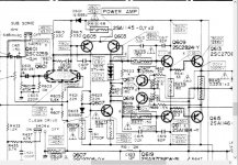
Finally looked at the circuit...
I see there is no vbe multiplier, just one of those multi diode packages (STV-4H) which I believe can be troublesome generally. If one of the diodes developed a fault and caused the voltage across the package to rise then the bias current would shoot up and cause overheating. Any such issue may be very intermitent.
Also worth checking the bias preset as old examples can develop problems such as poor wiper contact and intermitent/poor connection of the resistive track to the end terminal pins.
When you power up make sure to begin with the preset on minimum resistance. This will minimise initial bias current.
Attachments
Sometimes parts just fail. Like all of us, they reach end of life and something fails.
I think you may have a higher powered version of the SB-66. The schematic on HFE shows a 2 amp fuse and 50 volt rails. You indicate your unit has a 5 amp fuse and 70 volt rails.
You might want to double check the part number on those output transistors to be sure you are getting appropriate replacement parts. Wouldn't accept what is shown on the schematic.
I confirmed the part numbers on the transistors match the schematic. I have the Japan ONLY model; the schematic is for international. It's possible they made changes; my unit is "AUREX" which is supposedly a higher end Toshiba. Kind of like Acura is a higher end Honda I suppose!
Finally looked at the circuit...
I see there is no vbe multiplier, just one of those multi diode packages (STV-4H) which I believe can be troublesome generally. If one of the diodes developed a fault and caused the voltage across the package to rise then the bias current would shoot up and cause overheating. Any such issue may be very intermitent.
Also worth checking the bias preset as old examples can develop problems such as poor wiper contact and intermitent/poor connection of the resistive track to the end terminal pins.
When you power up make sure to begin with the preset on minimum resistance. This will minimise initial bias current.
OK, thanks, good advice. I'm going to hose down all pots, trim pots, connectors, switches, etc. liberally with Caig DeOxit while I have this apart. That stuff works great; expensive but worth it!
Finally looked at the circuit...
I see there is no vbe multiplier, just one of those multi diode packages (STV-4H) which I believe can be troublesome generally. If one of the diodes developed a fault and caused the voltage across the package to rise then the bias current would shoot up and cause overheating. Any such issue may be very intermitent.
Also worth checking the bias preset as old examples can develop problems such as poor wiper contact and intermitent/poor connection of the resistive track to the end terminal pins.
When you power up make sure to begin with the preset on minimum resistance. This will minimise initial bias current.
Thanks again; I have been doing some reading on setting bias in class A/B circuits since my last class in amplifiers was probably 1976 or so! The 1st page of the service manual gives us the answer here. I cleaned the trim pots then set them at their mid-points per the manual. If you look at the Emitter resistors; you will see they are 0.22 Ohm. The manual says to make sure bias current is below 30 mA after the unit has been on for 60 seconds. There are test points for this. Check me out on this: if I measure 6.6 mVolts across the test points this means I have 6.6 mV divided by 0.22 Ohms equals 30 mAmps. Without an O'scope; I won't be able to look at the "crossover" region. I remember setting the bias on my Yamaha receiver after changing output transistors YEARS ago. I didn't even have a DMM so I set the trim pots at mid-point. I then listened carefully to some very familiar recordings (amp. set on mono, 1 channel at a time) and carefully adjusted the bias pot. I just kept doing this over and over again until I obtained the "best" sound quality (indicating I had the bias about right and that the crossover distortion was "minimized"). What I DON"T know here is what range of bias adjustment these trim pots are designed to cover or allow. There is a voltage divider network in conjunction with the trim pots so I'm thinking and hoping the adjustment range is purposely limited by the divider. Regardless; I will slowly and carefully adjust these trimmers. I plan on leaving the amp on for several hours playing music and possibly tweaking the bias allowing for the new transistors to have some "break-in" time. No point in putting the covers back on for a few days just to make sure all is well!
Modern semiconductors can have slightly different 'turn on' voltages (Vbe) compared to the original parts due to differences in production and doping processes.
I would definitely begin with the preset on minimum resistance which means that R629 is effectively shorted out. That gives the lowest voltage possible between the base of the two driver transistors and consequently the lowest achievable bias current. Only if all is well should you then attempt to set a bias current.
(You have four base/emitter junctions to bias on before any current flows. These are the two output transistors and the two drivers and each will need around 500mv to 650mv approximately to do this. The diode chain provides three such multiples (so around 1.5 to 1.95 volts) and the series resistance (and preset) increase that further. Remember a difference of only a few millivolts is enough to go from non conducting to fully on for a transistor and this is why the circuit is a little critical on semiconductor types)
Using ohms law is the standard way to derive the figure and as you say 6.6 mv would equal 30 milliamp. Be sure to have no speakers attached when setting this as any slight DC offset totally skews the result due to DC current flowing in the speaker coil.
The trimmer should allow for control down to zero and upward to perhaps a few hundred milliamps. It is normal for the reading to vary wildly with temperature as the unit stabilises. Don't be tempted to go higher thinking it will sound better... it won't. Anything over a milliamp or so is enough to remove all audible distortion and so play safe when setting the current.
Free to a good home! Well, if you want this; you can have it for free, just pay for shipping! I spent about $100 on parts including shipping costs. To me; this thing isn't worth spending any more money on. It is about 40 years old; a decent amp but not great. If this were a classic Marantz, McIntosh, etc.; I would keep it and fix it.
There were several stages of transistors that got fried due to direct coupling I reckon. And, all the electrolytics are original (amazingly, they haven't failed yet!).
So, PM me if you would like to have this for just the cost of shipping. I have a Pay Pal account so I guess that's the easiest way to do this.
- Status
- This old topic is closed. If you want to reopen this topic, contact a moderator using the "Report Post" button.
- Home
- Amplifiers
- Solid State
- Aurex (Toshiba) SB-66 blows main fuse