Assuming the two fans are original and have the same part number then all you have to do is swap the wiring over and see if the fault stays with the fan or whether it moves to the other one.
Increasing the value of the cap will increase the arcing that occurs when the contacts close. You can mitigate that a little by adding a series resistance to the switch... buts trial and error and depends on the fan characteristics. You may or may not get the result you want.
Hi thanks for your reply.
They are a different fans to the originals and they need a bit more power to start them moving. They are 11watt 115v fans.
Please could you suggest what wattage value the resistor should be? would metal film be a good choice? i could buy a selection and try them out.
Thanks for your help : )
Its getting confusing ")
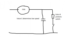
This was my idea. The extra resistor would help preserve the contacts if C was made bigger. Maybe a 68 or 82 ohm 2 watt.
The fact the fans are not original really does alter things because the design will have been 100% tailored to suit the correct fan fitment. So all bets are off and its down to trial and error and seeing if anything workable emerges. Your present fans may not be suitable.
This was my idea. The extra resistor would help preserve the contacts if C was made bigger. Maybe a 68 or 82 ohm 2 watt.
The fact the fans are not original really does alter things because the design will have been 100% tailored to suit the correct fan fitment. So all bets are off
and its down to trial and error and seeing if anything workable emerges. Your present fans may not be suitable.Attachments
So lets get the issue clear, to prevent going off on all kinds of tangents: there is no problem with the original circuit but you want, for some reason, to use other fans. These new fans do not run in the cold situation.
One thing you could check is whether there is a series resistance somewhere in the feed circuit to the fans that limits the voltage to them. That could be the case, for instance to limit max fan noise the amp produces.
Apparently the new fans need more voltage to run, so in this scenario this series R should be made lower in value.
There is also the possibility that those caps do double duty as 'series R' in the cold situation. That can be checked by increasing them in value and see whether the fan eventually does start up in the cold situation. A quick test would be to increase the cap to say 10uF.
BTW, I can understand that as a diy-er you want to play with stuff, but these things can lead to unexpected effects so are you sure you want to mess with this?
Jan
hi
I missed this post above.
There is no series R
in the cold state the cap surly can be the only thing reducing the speed. there is nothing else.
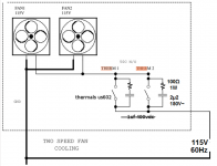
When cold the cap is the only path. And when hot the thermal closes and energy goes direct.
"I was not suggesting to insert a series R when there is none, obviously that would only make it harder for the fans to start.."
I did not say that, i was replying to Mooly I thought to put resistors across each thermal switch where the cap is so when the thermal is not closed (cold) the resistor will allow some more current to the fans so they will spin in the cold state.
but you mention a 10uf cap instead of a resistor . cool i shall try that.
Last edited:
Its getting confusing
This was my idea. The extra resistor would help preserve the contacts if C was made bigger. Maybe a 68 or 82 ohm 2 watt.
The fact the fans are not original really does alter things because the design will have been 100% tailored to suit the correct fan fitment. So all bets are off
Thanks Mooly I could not get the same fans as the original.
So I shall try 82 ohm 2 watt resistor with a 10uf cap at 400 vdc
and insert the resistor as you picture displays.
fingers crossed.
Last edited:
Firstly be careful...
Where are you going to get a 10uF cap suitable for this. You can't use an ordinary electrolytic, it has to be a non polarised motor run type.
Try adding another similar 1uF in parallel to what you have. Anything much over that is going to cause problems with arcing when the switch closes, even with a resistor.
Mooly is correct.
Have done this many times.
It's trial and error, add 1uF, if the new fan doesn't start, add another 1uF and so on until the desired speed is reached.
Adding up the values of the parallel capacitors gives you the new value.
10uF is way to large and a too big step to start with.
Use Y type film/foil capacitors preferable.
Firstly be careful...
Where are you going to get a 10uF cap suitable for this. You can't use an ordinary electrolytic, it has to be a non polarised motor run type.
Try adding another similar 1uF in parallel to what you have. Anything much over that is going to cause problems with arcing when the switch closes, even with a resistor.
hi , I have just seen that those non polarised caps are expensive. at 400vdc
I think i might just try another brand of fan again.
I thought this would be a simple case of soldering a resistor across the thermal. : )
Mooly is correct.
Have done this many times.
It's trial and error, add 1uF, if the new fan doesn't start, add another 1uF and so on until the desired speed is reached.
Adding up the values of the parallel capacitors gives you the new value.
10uF is way to large and a too big step to start with.
Use Y type film/foil capacitors preferable.
Hey thanks, and 1uf is much cheaper. : )
do I still need the resistor as in Moolys picture posted above?
- Status
- This old topic is closed. If you want to reopen this topic, contact a moderator using the "Report Post" button.
- Home
- Amplifiers
- Solid State
- schem error? and capacitor fail.