Service Manual of Pioneer's predecessor of A-757 MK-II version is here:
PIONEER A-757 SM Service Manual download, schematics, eeprom, repair info for electronics experts
(Pioneer Class-I, idle current servo "PA0016" in use - go to
https://www.diyaudio.com/forums/solid-state/202684-class-siblings-17.html#post2864279
and from post #2321 under
Bob Cordell's Power amplifier book)
But I don't find the service manual of the MK-I version (model name only "A-757").
Who can upload this ? And where is the main difference in the internal topology ?
Thank you very much for advices.
Now the service manual is here:
Pioneer A-757 Stereo Integrated Amplifier Manual | HiFi Engine
Attachments
-
 Pioneer A757-I.jpg69.4 KB · Views: 943
 -
 Pioneer A757-II.jpg148.8 KB · Views: 1,018
 -
 Pioneer A757-III.jpg41 KB · Views: 1,253
 -
 Pioneer A757 MK-II-I.jpg558 KB · Views: 2,155
 -
 Pioneer_A-757_Mark_II_-3.jpg290.9 KB · Views: 1,029
 -
 Pioneer-A-757-Mark-II-Vollverstarker-Bolide-Schwarz.jpg169.5 KB · Views: 616
Last edited:
There are additional threads concerning the MK-II version:
Pioneer A-757 MK2 schematic
PIONEER A-757 MARK II Schematic (under Chip Amps, wrong filed)
But they don't provide the wanted information.
Pioneer A-757 MK2 schematic
PIONEER A-757 MARK II Schematic (under Chip Amps, wrong filed)
But they don't provide the wanted information.
But I don't find the service manual of the MK-II version.
What about this one?
PIONEER A-757MKII ARP2033 Service Manual download, schematics, eeprom, repair info for electronics experts
Good Luck, even buying a service manual might be a challenge.
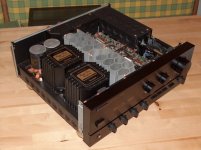
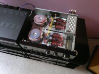
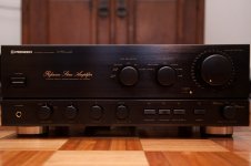
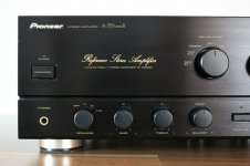
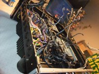
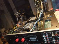
This integrated amplifier is the most complicated device ever (only in order for mechanical matters resp. disassembly).
Complete dismantling and assembly is definitely a challenge, but necessary to reach some areas around the input selection, volume control, RIAA MC/MM section and tone defeat switch - go to the attached images.
Now I am not able to perform a perfect assembly procedure. Where is to read the steps therefore ?
Thanks for an advice.
This links are not helpfull in this matter
Pioneer A757 repair, break & repair again - YouTube
Reparatur PIONEER A-757, PIONEER A-501 R | j-a-e.de
Attachments
-
 DSCF6441.jpg999.3 KB · Views: 452
 -
 DSCF6440.jpg988.8 KB · Views: 432
 -
 DSCF6439.jpg1,003.8 KB · Views: 394
 -
 DSCF6438.jpg1,003.9 KB · Views: 368
 -
 DSCF6437.jpg999.7 KB · Views: 360
 -
 DSCF6436.jpg998 KB · Views: 358
 -
 DSCF6435.jpg1,000.2 KB · Views: 915
 -
 DSCF6434.jpg1,006.2 KB · Views: 410
 -
 DSCF6433.jpg989.9 KB · Views: 444
 -
 DSCF6432.jpg995.9 KB · Views: 424
Last edited:
Hello tiefbassuebertr
Unfortunately, I can't help you with the issue, but as I have the A-777, I was able to obtain the service manual that also includes the A-676, the A-878 and an A-51, which I think is a version intended for other markets.
When viewing your photos, the interior and exterior of my A-777 is identical to that of the 575 MKII, so if you want the manual just send a pm.
Best regards
Carlos
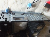
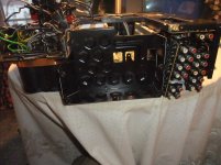
This integrated amplifier is the most complicated device ever (only in order for mechanical matters resp. disassembly).
Complete dismantling and assembly is definitely a challenge, but necessary to reach some areas around the input selection, volume control, RIAA MC/MM section and tone defeat switch - go to the attached images.
Now I am not able to perform a perfect assembly procedure. Where is to read the steps therefore ?
Thanks for an advice.
This links are not helpfull in this matter
Pioneer A757 repair, break & repair again - YouTube
Reparatur PIONEER A-757, PIONEER A-501 R | j-a-e.de
Which repair company resp. service center is able to completely disassemble and assemble this amplifier without any trouble?
I ask this so that I can give an address to the next guy who comes with this amplifier that is in need of maintenance, so that he can send the amplifier to those company.
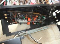
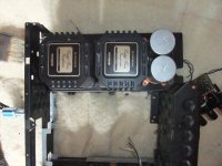
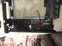
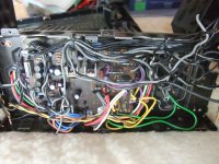
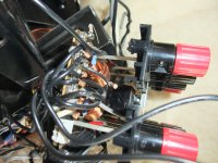
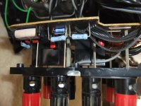
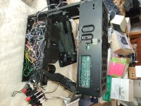
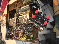
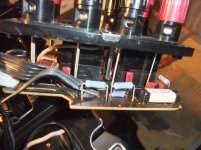
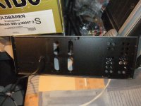
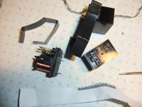
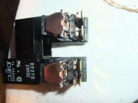
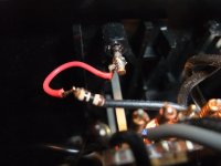
Desolder and opening Speaker Protect Relais
In contrast to most other amplifiers, this is also extremely complex and laborious with this model - go to the attached images.
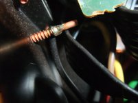
Last image shows the not good method when not using solder tags and instead this the cable is soldered directly to the screw that needs to be removed.
In contrast to most other amplifiers, this is also extremely complex and laborious with this model - go to the attached images.
Last image shows the not good method when not using solder tags and instead this the cable is soldered directly to the screw that needs to be removed.
Attachments
-
 DSCF6923.jpg1 MB · Views: 516
 -
 DSCF6925.jpg1,019.7 KB · Views: 292
 -
 DSCF6927.jpg1,004 KB · Views: 195
 -
 DSCF6929.jpg1,013.2 KB · Views: 222
 -
 DSCF6931.jpg1 MB · Views: 252
 -
 DSCF6933.jpg1 MB · Views: 311
 -
 DSCF6935.jpg1,011.1 KB · Views: 244
 -
 DSCF6937.jpg992.6 KB · Views: 349
 -
 DSCF6939.jpg917.2 KB · Views: 266
 -
 DSCF6941.jpg980.3 KB · Views: 234
Last edited:
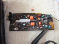
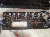
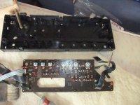
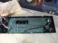
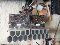
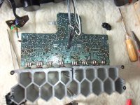
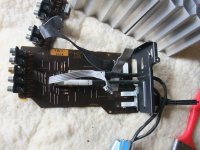
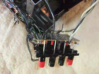
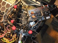
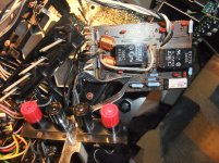
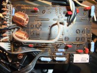
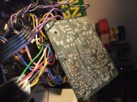
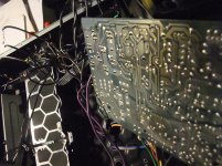
Voltage Regulator PCB
Images from the removed board (images from regulator PCB in assembled condition post #7 (Power caps replacement)
Pioneer A757 MKII - Power caps replacement?
Due to the lack of a solder tag, a resistor wire was torn off when the screw for speaker terminal was opened (last image).
Service-Manuals both from first Version and MK-II are here:
Pioneer A-757 Stereo Integrated Amplifier Manual | HiFi Engine
Attachments
Last edited:
concerning faulty PA0016 go to post #26 under
https://www.diyaudio.com/forums/pas...matic-self-biased-overview-3.html#post6443242
https://www.diyaudio.com/forums/pas...matic-self-biased-overview-3.html#post6443242
- Status
- This old topic is closed. If you want to reopen this topic, contact a moderator using the "Report Post" button.
- Home
- Amplifiers
- Solid State
- Pioneer Integrated Amplifier A-757 (A757) and A-757 MK-II - what differences ?