Mouser has one heck of a lot of orangesGrrrr. . . part selection isn't like going to the market to shop for oranges.
") and apples well that is over the top.
and apples well that is over the top.Oops, I forgot I needed a bunch more zeros -- skipped 'nano' on my way to micro! <snip>
Hi the list looks good. You choose better buffer caps which is a very good choice. I have noticed you choose 5 mm caps but my last hint is that you should measure and check if the new parts all fit where the old ones were. Often height is overlooked with buffer caps but modern 10,000 µF caps are almost always shorter than the old ones. Many manufacturers add extra PCB pads to be able to use various types of caps. This is the most optimal situation when you have such a device. For instance the input caps look larger than 5 mm. There are Wima versions in 7.5 mm and 10 mm pitch. Same dieelectric but higher voltage rating which is OK.
7.5 mm or even 10 mm means you can upgrade to better dieelectrics like MKP or Polyphenylenesulphide (PPS) as better film caps are larger than the standard polyester MKS/MKT. Forgot that last one, they are also good. MKS/MKP/PPS can be found in 5 mm, 7.5 mm etc etc. You just have to search. It is customary to use better dieelectrics for signal coupling and filtering.
Imagine your car having 17" wheels and you buying 20" tires. It is all very simple.
I'm running on the United States power at 120VAC 60Hz.
Please see the schematic and adjust your RB-850 to 120V is it is still on 110V setting. Some manufacturers choose caps with voltage ratings that are almost met. When mains voltage is higher then the caps can suffer from overvoltage (Musical Fidelity comes to mind).
* Work tidy, don't rush and make it look OK too. Drill the holes for the buffer caps very carefully and slowly in the existing slice holes and please do not use a too large diameter drill. I think you need a 1.5 mm drill. Check polarity of the polar caps 3 times before soldering them, preferably with a coffee break between checks. Don't laugh! It happens to everyone now and then and it will cost more time and money to fix. When you work tidy the device will be just as reliable as it used to be but with better sound quality.
Last edited:
Please see the schematic and adjust your RB-850 to 120V is it is still on 110V setting. Some manufacturers choose caps with voltage ratings that are almost met. When mains voltage is higher then the caps can suffer from overvoltage (Musical Fidelity comes to mind).
I think my original picture didn't show it correctly. Here are some closeups of the board pitch and mains transformer wiring. The 110V leads are capped off from the factory. When I took a second look my heart stopped for about a second until I saw the double wrap around the leads. Dodged that one!
An externally hosted image should be here but it was not working when we last tested it.
I need to go back to my shopping list and make sure the 5mm pitch works for almost all but C601/C602. . .Disregard the hot melt glue. It doesn't always look great (actually never) but it works for me to secure items. Those wires leaving the board are for the bias resistor. I don't like the drift of multi-turn pots so I settled on standard resistor values that put the bias within a couple of mV of each other (channels) I think it is currently set at 330 Ω and 270 Ω. Those values are setting about 5mV across the output resistor and resulting in about 23mA of bias current. A jumper instead of the resistor results in about 20 mV and 91 mA across the .022 Ω output resistor. I will probably need to adjust them when the new caps are installed -- I expect some shift. There is a picture of the resistors in the first post. [Rotel_1021.JPG]
An externally hosted image should be here but it was not working when we last tested it.
An externally hosted image should be here but it was not working when we last tested it.
Last edited:
C601 / C602 Input Cap with 10mm Pitch
I have reselected the input cap to be a 10mm pitch. I remeasured the board holes and all are 5mm except the
input cap.
C601-602
1 µF 100V Film? silver cube [SIGNAL INPUT] 10mm Pitch
Replacement (Not any longer)
5mm Pitch
1 µF 100V 5% WIMA Polyethylene Terephthalate (PET) #MKS2D041001K00JSSD ($0.74 ea)
MKS2D041001K00JSSD WIMA | Mouser
Switch to this replacement
10mm Pitch
1 µF 100V 5% WIMA Polyethylene Terephthalate (PET) #MKS4D041003F00JSSD ($0.82 ea)
MKS4D041003F00JSSD WIMA | Mouser
Last edited:
Mouser has one heck of a lot of oranges
It is sometimes very difficult to tell the difference between items. Many parts look similar (they reuse pictures) and spec/model number wise. You could easily order 10,000 of the wrong item. At least we have a selection. Reading on Paul Klipsch and his part selections for the early K-horns, he had to make some pretty strange adjustments to work with the parts available.
rsavas -- you should get an avatar picture. For me it is a quick way to scan a thread and see who has replied. It is fun also to come up with something unique. I had an eyeball for years and just recently changed it to my ugly mug. . .just older but not always wiser.
Last edited:
Glad to see you are actually measuring what you plan on replacing. We are so fortunate these days, in earlier times, it was a PITA sourcing, buying and identifying components. These days I can get a design done in record time, design, order pcb from China DHL express, parts from Mouser, FedEx express.
It is all in the details and some patients. Good luck with you re-build.
Avatar for another time.
It is all in the details and some patients. Good luck with you re-build.
Avatar for another time.
Old Capacitors: 10000µF 50V at 2" (50.8mm) Dia., and 1-5/8" (42.5mm) High
There is room for a capacitor of 2-3/8" (60.3mm) High [board to lid height]
Will replace with Nichicon Snap-in LKG1H103MESCBK LKG1H103MESCBK Nichicon | Mouser

There is room for a capacitor of 2-3/8" (60.3mm) High [board to lid height]
Will replace with Nichicon Snap-in LKG1H103MESCBK LKG1H103MESCBK Nichicon | Mouser
Last edited:
Big question about capacitors!
Rotel RB850 Capacitor Replacement Project
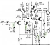
The capacitors I pulled from the amp board and the schematic/silkscreen don't seem to match.
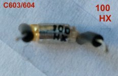
C603 is clearly 100 HX (see attached images)
On the schematic it shows 100P, while on the silkscreen it shows 100 and a polarity mark.
Generally, I consider a capacitor listing without a value to be a µF value.
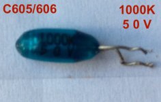
C605 is clearly 1000K
The K is usually 10% tolerance with the three digit + letter coding for capacitors.
Yet, on both the schematic and silkscreen it is listed as 1000P. That doesn't seem to jive!
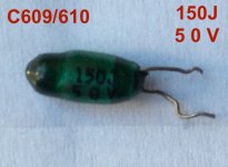
C609 is clearly 150J (15pF 5%)
According to standard practice 150J should be 15pF. Yet both
the schematic and silkscreen are indicating 150P. Did Rotel
put a lower value in the amp? Did the schematic and/or
silkscreen get the wrong data and put a P where it should
have been a J? Something is not very clear.
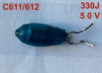
C611 is clearly 330J (33pF 5%)
See C609 description above. Additionally, if the wrong part had
been put in, the amp ran fine. Would placing a 10x reduction in
capacitance in this circuit be harmful? Could this have been a cost
cutting measure? Seems like a large difference.
If someone can give a some advice that would be great.
I really appriciate the previous help received here.
PS - figured out how to attach thumbnails -- looks a little better that my previous posts
Rotel RB850 Capacitor Replacement Project
The capacitors I pulled from the amp board and the schematic/silkscreen don't seem to match.
C603 is clearly 100 HX (see attached images)
On the schematic it shows 100P, while on the silkscreen it shows 100 and a polarity mark.
Generally, I consider a capacitor listing without a value to be a µF value.
C605 is clearly 1000K
The K is usually 10% tolerance with the three digit + letter coding for capacitors.
Yet, on both the schematic and silkscreen it is listed as 1000P. That doesn't seem to jive!
C609 is clearly 150J (15pF 5%)
According to standard practice 150J should be 15pF. Yet both
the schematic and silkscreen are indicating 150P. Did Rotel
put a lower value in the amp? Did the schematic and/or
silkscreen get the wrong data and put a P where it should
have been a J? Something is not very clear.
C611 is clearly 330J (33pF 5%)
See C609 description above. Additionally, if the wrong part had
been put in, the amp ran fine. Would placing a 10x reduction in
capacitance in this circuit be harmful? Could this have been a cost
cutting measure? Seems like a large difference.
If someone can give a some advice that would be great.
I really appriciate the previous help received here.
PS - figured out how to attach thumbnails -- looks a little better that my previous posts
Attachments
Last edited:
Older japanese caps often have the real value printed on them. In case you have a lack of experience or knowledge just measure them and be sure.
Since modern film caps can be large in value but are also in 5 mm pitch I would use 1 µF MKT for C605 (only that one and only because of its function).
P = picoFarad.
Wrong. Assumption is the mother of *******.
Since modern film caps can be large in value but are also in 5 mm pitch I would use 1 µF MKT for C605 (only that one and only because of its function).
P = picoFarad.
Generally, I consider a capacitor listing without a value to be a µF value.
Wrong. Assumption is the mother of *******.
Last edited:
So, you might grab a 330J film capacitor and it could be a 33pF with 5% or a 330pF with 5% tolerance -- just depends who made it and when it was made. That just seems like a recipe for disaster! I will move forward and ignore that voice in my head that says 'this is wrong.' 
It's function being to bypass the 100µF (C607) electrolytic cap in the feedback to ground filter?
Thanks for the input.
I would use 1 µF MKT for C605 (only that one and only because of its function).
It's function being to bypass the 100µF (C607) electrolytic cap in the feedback to ground filter?
Thanks for the input.
Attachments

Last edited:
All Thread Images for RB850 Rebuild part 1
Parts List
View attachment _Rotel_RB850_Parts_List.txt
RB850 Redraw

RB850 Schematic

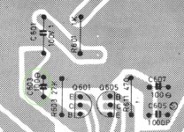
C603/604 Silkscreen

C603/604

C605/606

C609/610

C611/612

RB850 Schematic 1

RB850 Schematic 2

Parts List
View attachment _Rotel_RB850_Parts_List.txt
RB850 Redraw
RB850 Schematic
C603/604 Silkscreen
C603/604
C605/606
C609/610
C611/612
RB850 Schematic 1
RB850 Schematic 2
Last edited:


Shout out and thanks to Jean-Paul for taking the time and explanations on this thread. Redid my pair of 850s used in mono mode, film caps are brilliant. The lead spacing on the main filter caps is a consideration, I made the ones I purchased work, but took a little convincing. These 80s caps were absolutely tired, I now have a bright, present punchy set of monoblocks now, totally worth the $100 (eight 10k uf add up).
- Home
- Amplifiers
- Solid State
- Rotel RB850 Rebuild 2019