I’m not sure how you came up with the figures above but it doesn’t matter what the load is.
The load in my example matters only as far as determining the bias current, which determines the required capacitance. I thought that much was obvious.
Which figures are you questioning?
If you go back to basic principals and look only at the transformer and rectifier/capacitor bank it will make this a lot easier. Look at equal energy storage with 2 scenarios -Same transformer primary but one with a low voltage secondary and one with a high voltage secondary.
Hmm. It looks like not only you are right, but also that i am wrong ")
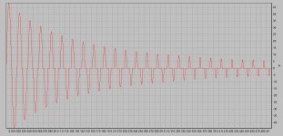
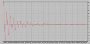
Ignoring everything else and just looking at caps with equal energy storage:
1. 100mF/60v
2. 2.25mF/400v
I get these pictures for the currents in the transformers secondaries. It makes perhaps more sense to get the RMS values for the first 100mS which are:
1. 28A
2. 14A
Of course these are transformed back to the primaries, so 1 is divided by 3.83 and 2 is multiplied by 1.23
Attachments
Hmm. It looks like not only you are right, but also that i am wrong
Ignoring everything else and just looking at caps with equal energy storage:
1. 100mF/60v
2. 2.25mF/400v
I get these pictures for the currents in the transformers secondaries. It makes perhaps more sense to get the RMS values for the first 100mS which are:
1. 28A
2. 14A
Of course these are transformed back to the primaries, so 1 is divided by 3.83 and 2 is multiplied by 1.23
Yes, the transformer action is the key to understanding this. I thank you for being patient in this discussion. Right/Wrong is not so important as learning from each other. Transformers are really amazing devices and sometimes we take them for granted.
Regards
Brian
And i thank you for pointing me in the right direction, which was contrary to my gut feeling.
The charging pulses in the graphs decrease at different rates as the active resistance is different. This is due to the higher ESR of the smaller caps and the higher DCR of the tube transformer secondary. I was expecting these effects to be much stronger.
The charging pulses in the graphs decrease at different rates as the active resistance is different. This is due to the higher ESR of the smaller caps and the higher DCR of the tube transformer secondary. I was expecting these effects to be much stronger.
Thanks guys for the discussion which is turning out to be a tutorial for me.
So here can I see that a Class A amp might cause the breaker to trip due to it’s initial current & charging demands sort of like an aircon compressor when it kicks in. Am I correct in my thoughts ? What I do not understand is that I’ve read of amps drawing 20amps of 50 amps etc , now where does this come from when the power socket at the wall only provides say 5 amps. If Im not mistaken my total household supply is only rated at 30 amps 230v.
Thks
So here can I see that a Class A amp might cause the breaker to trip due to it’s initial current & charging demands ...
This doesn't hold true solely for class A, but for any amp with a big power supply. I've experienced big class B tube amps without inrush current limiter tripping the contact breaker as well.
Best regards!
Am I correct in my thoughts ?
Yes and no. The discussion above was pretty much theoretical.
Real life SS amps with huge capacitor banks will certainly have some type of soft start circuit which greatly reduces the surge.
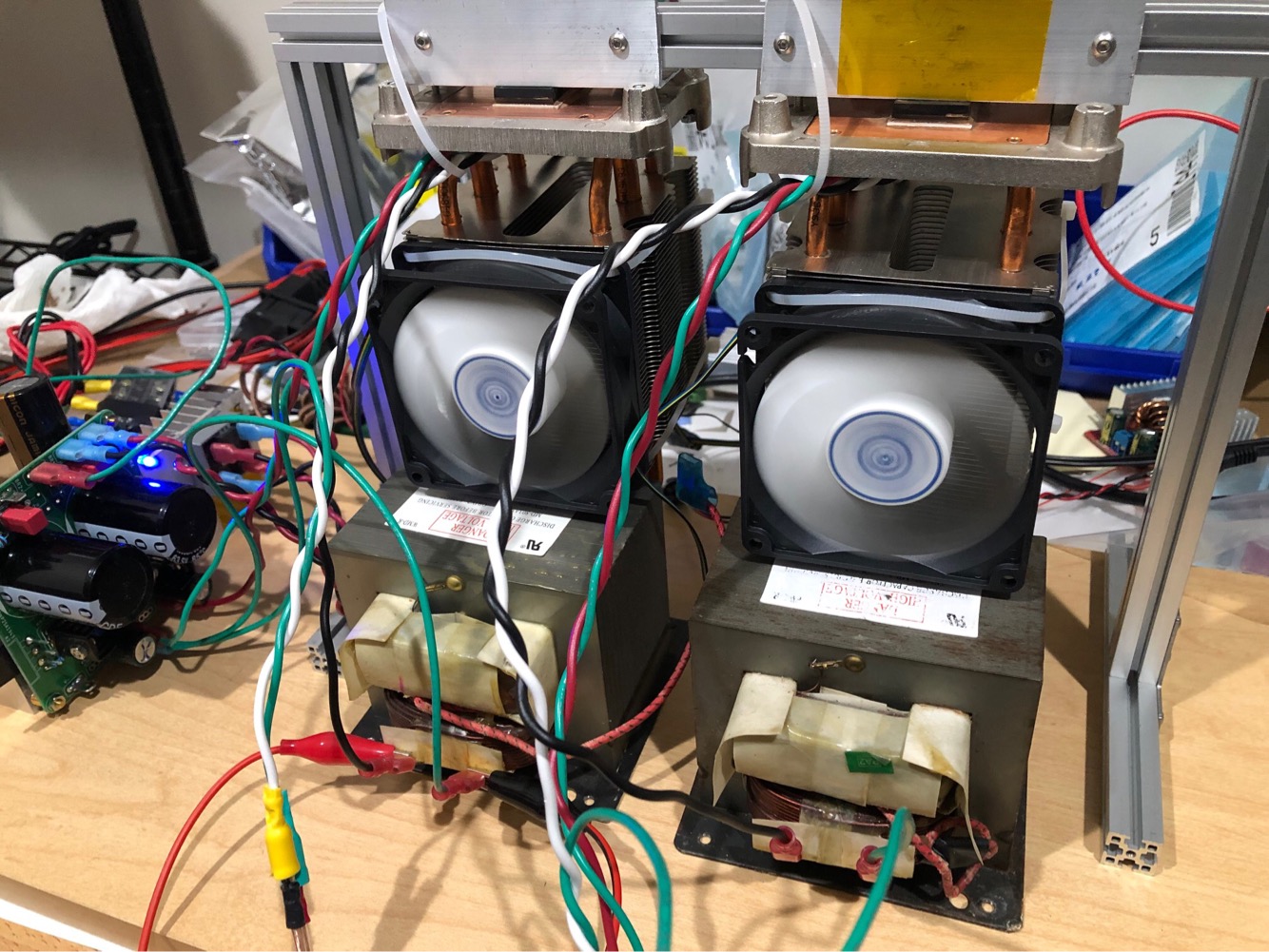
Real life high power tube amps will have something similar, or at least use a power transformer with a much greater winding resistance than what i used in the simulation. As i had already used a 6ohm primary transformer for the SS case it was only fair to use a similar one for the tube amp, with a slightly higher resistance for the secondary. Such a transformer is certainly a rarity in the tube world.
Very high power rating amps will not produce their full power with normal domestic wiring. D'Agostino Relentless comes immediately to mind.
Thanks guys for the discussion which is turning out to be a tutorial for me.
So here can I see that a Class A amp might cause the breaker to trip due to it’s initial current & charging demands sort of like an aircon compressor when it kicks in. Am I correct in my thoughts ? What I do not understand is that I’ve read of amps drawing 20amps of 50 amps etc , now where does this come from when the power socket at the wall only provides say 5 amps. If Im not mistaken my total household supply is only rated at 30 amps 230v.
Thks
That 30 amps is what your main circuit breaker will supply continuous without tripping.If you put a short circuit on your 30 amp breaker the current will be in the thousands (till the breaker trips,a very short time).
If you use an NTC thermistor on the mains leading to the power trafo (say NTC 8D-20)
https://datasheet.lcsc.com/szlcsc/NTC-Thermistor-5R_C69391.pdf
It will provide about 8ohms resistance upon initial power up, as it heats up it drops to about 0.5ohm. They run very hot, but that's not a problem as they are designed to do so. I don't have any power dimming and using to power two 300VA transformers putting out 5amps each current at 37v. I think for more current, you can use higher value NTC's and parallel them to get the current you need. It's not hard.
Btw, if you want tube like sound at 50wrms, you don't need a tube amp Build a MOAMOFO (Mother of All MOSFET Followers) as it has the harmonic profile of a tube amp and the power of a SS amp without the HV or output trafos. Just a surplus microwave oven transformer for a reactive load on the MOSFET and lots of current and voltage. More info here:
Build This MoFo!
Last edited:
....a Class A amp might cause the breaker to trip ... like an aircon compressor when it kicks in. ... I’ve read of amps drawing 20amps of 50 amps etc , now where does this come from when the power socket at the wall only provides say 5 amps. ....
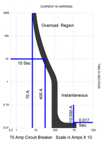
As Scott and others say: you can pull HUGE current for short time. It takes real time for a wire to catch fire and burn down your house. I have a well-pump on a 20A breaker. It pulls 44 Amperes for a part second. The breaker never blows.
Attached are time-curves for ordinary circuit breakers. A "30A" breaker should never blow at 30.0A. It will carry 80A for most of a minute, 200A for 8 seconds. 8 seconds at 200A should be more than enough to cold-charge any sane capacitor bank.
The peak charging current is limited by the economics of transformers. Small trannies have high losses and may not suck even 5X their max rating. Over 100VA the losses may be 5% or even 2%, so 20X or 50X the max running current may be possible.
Given a 230V 30A line, your max continuous power is 6900 Watts. Class A efficiency is ideally 50% but there's losses everywhere. You could still have 1,600 Watts of rated A audio output on this power line.
Your real limit is HEAT. A 1,000W electric fire warms a room. An amplifier sucking 6,900 Watts steady is a BIG electric "fire". It would heat my whole house in freezing weather. In summer it would be intolerable.
Next limit is Electric Bill. 6,900W at my electric rate is US$1.31 per hour, say $5 a day and $150/month. Double what I pay to run the whole house.
Attachments
This electronic component part named C69391 from NTC thermistor should meet your needs
the following link : Shenzhen Ruilongyuan Elec NTC Thermistor 5Ω, Shenzhen Ruilongyuan Elec Shenzhen Ruilongyuan Elec NTC Thermistor 5Ω in Stock available. Buy Shenzhen Ruilongyuan Elec NTC Thermistor 5Ω with best price from chipmall.com | Chipmall.com
It will provide about 8ohms resistance upon initial power up, as it heats up it drops to about 0.5ohm. They run very hot, but that's not a problem as they are designed to do so. I don't have any power dimming and using to power two 300VA transformers putting out 5amps each current at 37v. I think for more current, you can use higher value NTC's and parallel them to get the current you need. It's not hard.
- Home
- Amplifiers
- Solid State
- 50 watt SS Class A vs 50 watts Tube Class A