Dear readers,
a audio friend asked me to modify his solid state amp.
i did some modifications on pre amplifiers (C’s, volume stepped attuenators and R’s) and that worked out pretty good so he asked me to see if i could make his Kron amplifier to sound a bit more ‘smooth’ (sounds a bit ‘sterile’ now.
I looked at the power bank C’s and thought of replacing these with Nichicon FG or others (advice?)
but thought that C’s and R’s in the signal path might be more worthwile.
Some help and advice would be very much appreciated as i have no experience with amplifiers.
Thanks!!
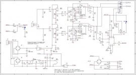
I see from the picture that the amplifier does use the TDA7250 chip. The feedback resistors from the outputs to pin 20 and pin 11 have a big influence on the overall sound of the amplifier, you may start to increase the values slightly, to reduce the global feedback. You could also change the power transistors. Be careful with the modifications, this chip is eager to become a HF oscillator / tweeter killer. The ceramic capacitors you see all over the place are there to increase stability. It seems to be about 15 years old, a total exchange of all the electrolytics may be useful (test the capacitors to see if there is degradation). You will find useful informations about this chip by using the search function of this forum.

I see from the picture that the amplifier does use the TDA7250 chip. The feedback resistors from the outputs to pin 20 and pin 11 have a big influence on the overall sound of the amplifier, you may start to increase the values slightly, to reduce the global feedback. You could also change the power transistors. Be careful with the modifications, this chip is eager to become a HF oscillator / tweeter killer. The ceramic capacitors you see all over the place are there to increase stability. It seems to be about 15 years old, a total exchange of all the electrolytics may be useful (test the capacitors to see if there is degradation). You will find useful informations about this chip by using the search function of this forum.
Thank you,
i take it that you refer to the pin 11 and 20 of the chip itself and the feedback resistors which are connected to these pins?
Increasing the value of Ohms and not just Wattage i presume?
What kind of percentages are we talking about?
Would it make sense to increase Wattage of these resistors also?
Would it make sense to replace the green 10K resistors for ‘better’ ones, like Takman 2W e.g.?
Which brand of electrolytic would make sense? for the smaller Voltages maybe Elna Silmic and for the power bank C’s any recommendation? (high or low ESR?)
These are now Korean cheapo’s.
Thanks again!
(purpose remains a tad smoother/warmer sounding amp)
Insert a tube buffer between pre- and amp
Mona
Do you mean also on the chip itself?
There is no preamplifier part in this amplifier, but i take it that you are aware of that and you are referring to the chip also, any idea or example of how i should proceed with such an endeavor? sounds neat but wouldn’t know where to start, please elaborate, Thanks!!
Yes, I am referring to the feedback resistor between pin 11 and the output (speaker), and between pin 20 and the output. There is no power on those pins, so you need to increase only the ohm value by 20% (as example) and check if the result is going in the desired direction. The green power resistors are 0.1 ohms (0.15 ohm is the datasheet recomended value) and I would not change them. The marking is R10 = 0.10 ohm Keramik. The capacitor choice is not critical. I use Vishay, Nichicon or Panasonic on this kind of recap jobs because they have good quality and comparatively low price. I would not waste better capacitors on this amplifier because any TDA7250 based amplifier will only improve up to a limit, no matter what amount of money and parts you throw at it. It was a good at the time but today I believe that we have better parts and designs.
Something like this ?Do you mean also on the chip itself?
There is no preamplifier part in this amplifier, but i take it that you are aware of that and you are referring to the chip also, any idea or example of how i should proceed with such an endeavor? sounds neat but wouldn’t know where to start, please elaborate, Thanks!!
Mona
Attachments
That requires a full redesign and basically a new build.a audio friend asked me to modify his solid state amp..... he asked me to see if i could make his Kron amplifier to sound a bit more ‘smooth’ (sounds a bit ‘sterile’ now.
Just changings partys *brend* will do nothing of the sort, no matter what Marketing Department or esoteric "Audio" magazines say, both are based on expectation bias and placebo effect.
Nice caps buy why woud they make an amp "less sterile" is beyond me.I looked at the power bank C’s and thought of replacing these with Nichicon FG or others (advice?)
See above.but thought that C’s and R’s in the signal path might be more worthwile.
Parts are not "warm" or "sterile" or "spacious" or "musical" or whatever by themselves, they are bricks in a house and with them you may build very different kinds of buildings, but replacing some here and there with same size ones (or they wouldn´t fit) does not turn a garage into a kitchen or bedroom.
Something like this ?
Mona
Thank you for posting, as this ‘modification request’ is not for myself, i doubt that this much work is feasible, but thanks anyway!!
That requires a full redesign and basically a new build.
Just changings partys *brend* will do nothing of the sort, no matter what Marketing Department or esoteric "Audio" magazines say, both are based on expectation bias and placebo effect.
Nice caps buy why woud they make an amp "less sterile" is beyond me.
See above.
Parts are not "warm" or "sterile" or "spacious" or "musical" or whatever by themselves, they are bricks in a house and with them you may build very different kinds of buildings, but replacing some here and there with same size ones (or they wouldn´t fit) does not turn a garage into a kitchen or bedroom.
I get what you are saying and wouldn’t dispute, however i do have positive experience with changing coupling caps and some resistors in signal path for higher Wattage and a bit ‘better’ (Takman and Shinkoh e.g.) as with stepped attenuators in stead of the standard logarithm volume pots, so to some degree i ‘believe’ in modification, this was however solely with pre amplifier work, i have never modified any amplifier before, hence this thread.
But appreciate your post and fully understand what you convey.
Thanks.
This looks like it has been built from a kit. I have no idea why whoever built it decided to put the TIP142 devices on wires.
Improve the power supply capacitors perhaps, but otherwise there's not much worth upgrading. A lot of the sound quality is down to the TDA7250 chip itself, and as this is now obsolete you really dont want to risk messing about too much.. as if you blow it, a (genuine) replacement will be hard to get.
Any worthwhile modification (using better outputs than the TIP142/147 darlingtons, in a CFP configuration for example) would require extensive modification to the point where it would be better to make a new PCB.
Another alternative is to see what the power supply voltages are, and perhaps build another kit amplifier of superior performance into the chassis
This looks like it has been built from a kit. I have no idea why whoever built it decided to put the TIP142 devices on wires.
Improve the power supply capacitors perhaps, but otherwise there's not much worth upgrading. A lot of the sound quality is down to the TDA7250 chip itself, and as this is now obsolete you really dont want to risk messing about too much.. as if you blow it, a (genuine) replacement will be hard to get.
Any worthwhile modification (using better outputs than the TIP142/147 darlingtons, in a CFP configuration for example) would require extensive modification to the point where it would be better to make a new PCB.
Another alternative is to see what the power supply voltages are, and perhaps build another kit amplifier of superior performance into the chassis
Interesting info, thank you!
Would it be feasible as discussed in an earlier post to increase the Ohm value on the resistors on pin 11 and 20 of the TDA7250?
I will replace the power supply caps but would like to change some other small things too, if it was my own amp i would certainly go the route you describe but that is not the case, thank you.
Thank you,
i am to change the power supply caps, they are rated 2200uF, 50V, 6 pieces, Jamicon made.
Would it be beneficial to increase the capacitance?
Or is it better to leave that be?
Also can i raise the Voltage spec? As i was looking at the KG type Nichicon caps and in 2200uF they have only 100V caps.
Or would any of you have a recommendation for another brand/type?
Thank you!
Yes you can, but it would not bring any advantage. I use higher voltage capacitors on vintage equipment, to preserve the look of the amplifier.
Thanks!
- Status
- This old topic is closed. If you want to reopen this topic, contact a moderator using the "Report Post" button.
- Home
- Amplifiers
- Solid State
- help needed with modifying a Kron solid state amp