Hi, new member with an old A level in CDT and a Maplin's soldering iron trying to fix my gf's A500 before the weekend.
Been reading the threads and found SAP15 U202 to be blown so decided to rip them all out to save future silences.
Also ordered new STD03s from profusion as recommended here.
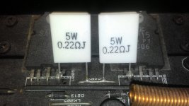
Q1: My local shop does not have .22R in 3-5W so is it Ok to go with other ranges?
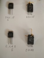
Q2: The STD03s from profusion are missing a leg, in both cases the S leg which I think is the emitter without resistor. So do I bend the STD03 E into the original S hole and then take a resistor off that and put it in the E hole?
I'm just confused about the mechanics of soldering in the STD03 when it is missing a leg and there needing to be a .22ohm resistor.
Cheers,
U
Been reading the threads and found SAP15 U202 to be blown so decided to rip them all out to save future silences.
Also ordered new STD03s from profusion as recommended here.
Q1: My local shop does not have .22R in 3-5W so is it Ok to go with other ranges?
Q2: The STD03s from profusion are missing a leg, in both cases the S leg which I think is the emitter without resistor. So do I bend the STD03 E into the original S hole and then take a resistor off that and put it in the E hole?
I'm just confused about the mechanics of soldering in the STD03 when it is missing a leg and there needing to be a .22ohm resistor.
Cheers,
U
Attachments
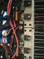
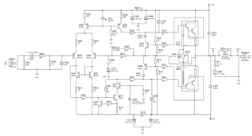
The A500 circuit shows all 5 pins are used with the original devices. So yes, you connect the new device emitter to the S position and add the 0.22 from there to the originals emitter.
Anything larger than 5 watt will be getting to large physically. 2.5 watt vitreous enamel types would be fine and not to large.
Anything larger than 5 watt will be getting to large physically. 2.5 watt vitreous enamel types would be fine and not to large.
Ok, I've made the bulb tester and it works with other devices and I've soldered everything together but I'm now stuck on the Idle current adjustment procedure.
According to the manual "When replacing SAP15 output pair, reset bias current by adjusting RV201 while monitoring the voltage between S and E of the transistor"
Well RV201 is connected to both U201 and U202 so I don't know where to put the meter probes to make a measurement.
And when I've adjusted the bias for both channels how should I proceed. Add some speakers and slowly increase the volume still with the bulb tester?
Also I've not replaced any other parts as RV201 and RV202 both worked in circuit so as they've not blown I'm hoping nothing else has.
Powering up at the moment the bulb tester flashes as I turn the amp on then it goes dark so I think there is no short or further burning out.
Sorry if this is all basic stuff.
Any help would be greatly appreciated.
If setting these biases works I'll be over the moon. Then it will only be a matter of how long my dodgy soldering lasts.
Cheers,
U
The bulb tester is really to prevent catastrophic failures during initial testing. What you describe sounds good so far.
The bulb wont allow high audio levels, in fact its best not to try. If the amp all works OK with the bulb, then you should reset the bias again when on full mains.
The A500 manual says to adjust for 13mv across either of the 0.22 ohms. That equates to around 60ma current flowing. No signal and no speakers connected for performing that adjustment.
I was adjusting bias resistor and getting no voltage across on S and E for either channel on any STD03 and the other thread mentioned this could be because of VI protection transistors.
Do you know which ones those are on the diagrams?
Original fault was one channel blown after party then the other went after using amp with one speaker for a while.
Also looking this morning I can see clearly why one channel wasn't working. It's because I put in the STD03P wrong. I'm taking the part out now hoping that whatever the VI protector is that it protected this part so I don't have to order another one.
It ain't easy fixing these things.
Attachments
It ain't easy fixing these things.
Hmmm...yes it is
") ...the image shows how I repaired my amplifier. In my case, only the internal emitter resistor burned, so I just added the external one (it is also advisable to do this with fully-functioning transistors because the internal emitter resistors have to low power dissipation)
...the image shows how I repaired my amplifier. In my case, only the internal emitter resistor burned, so I just added the external one (it is also advisable to do this with fully-functioning transistors because the internal emitter resistors have to low power dissipation)Attachments
- Status
- This old topic is closed. If you want to reopen this topic, contact a moderator using the "Report Post" button.
- Home
- Amplifiers
- Solid State
- Cambridge A500 replacing S