Hello,
This is my first shot at laying out a PCB, so please bear with me in this. I'm sure there are a lot of idiotic errors, but all my experience is with point-to-point wiring (and I'm certainly not all that great at that either).
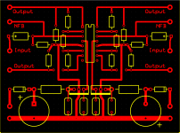
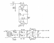
So this is a design for a solid-state phase splitter (for a tube amp, but that's a bit irrelevant). I know there are probably better chips than the AD713, but I have a whole bunch of them leftover from another project. It's probably not a perfect design. (Ideas are welcome, but I mostly want suggestions for the PCB). I will obviously breadboard the whole thing before etching a PCB, but it does simulate well.
This is designed to work off a 60VCT transformer, so there is a power supply section on the bottom half of the board. As you can see there is one place where a jumper will be needed for the output line to cross over the ground line. Not ideal, but I can live with it. Also, schematic error, those are 7815 and 7915 regulators, and the rails are +/- 15 Volts, not +/- 18.
Thanks for the suggestions!
This is my first shot at laying out a PCB, so please bear with me in this. I'm sure there are a lot of idiotic errors, but all my experience is with point-to-point wiring (and I'm certainly not all that great at that either).
So this is a design for a solid-state phase splitter (for a tube amp, but that's a bit irrelevant). I know there are probably better chips than the AD713, but I have a whole bunch of them leftover from another project. It's probably not a perfect design. (Ideas are welcome, but I mostly want suggestions for the PCB). I will obviously breadboard the whole thing before etching a PCB, but it does simulate well.
This is designed to work off a 60VCT transformer, so there is a power supply section on the bottom half of the board. As you can see there is one place where a jumper will be needed for the output line to cross over the ground line. Not ideal, but I can live with it. Also, schematic error, those are 7815 and 7915 regulators, and the rails are +/- 15 Volts, not +/- 18.
Thanks for the suggestions!
Attachments
Last edited:
")
I mostly want suggestions for the PCB.
You want nonpolar coupling capacitors at the inputs. The DIP package only has 14 pins, so check all the pinouts, there is a problem there. Move C8, C9 closer to the IC.
The value of R5 is too high. You may need a Zener preregulator to use such a high DC input voltage, because the load current is not precisely defined.
Is your transformer dual secondaries, or center-tapped? If it is center-tapped, you'll need to rework the grounding, as then there is only one high current ground return point.
Last edited:
Thanks,
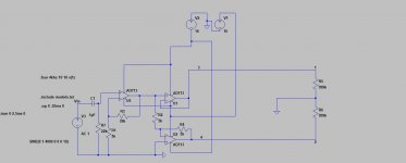
The amp this was drawn for is now on its third driver board design (finally working... I think), and I decided to put the power supply on a separate board. Ultimately I've done this on perfboard since I've been changing the design a fair bit to make it perform how I want.
Yeah, I noticed the pinout on the regulators. Forgot that the 7915 has a different pinout from the 7815. I'll design a PCB when I've gotten enough time on the amp to feel confident in my driver. Attached is the schematic (using SPICE) of the new version of the driver.
Attachments
Many good points, but wasn't there a 16pin version of the opamp too. Just 2 extra pins in one end?
Yep. All of mine are the 14 pin version, but at the time I drew that board layout I was about 40 miles away from my shop so I drew the board so it could take either type.
Side note: I don't suggest paying the $14 each that the AD713 costs. It's better than a TL074, but not that much better. Mine are leftover from a friend's Harrison console project in the mid 90s. I believe he used them to replace the original 4741 chips. He said they didn't cost nearly this much when he bought them, since he put about 200 of them into the desk.
- Status
- This old topic is closed. If you want to reopen this topic, contact a moderator using the "Report Post" button.
- Home
- Amplifiers
- Solid State
- Solid-State Driver PCB Layout