Hi guys a friend recently asked me to look at an old amp that her husband gave her back in the 70's as a anniversary present and now he is gone.
It was pretty badly blown ( black on the pcb) etc.
I replaced all the blown caps transistors and resistors and have only put the output transistors back into the right channel so far.
I didnt touch the zeners or power diodes or ceramic caps.
I input a 1000hz sinewave but the output is very low with no power at all and clips very early
The output transistors get hot pretty fast aswell.
Any suggestions as of where to look first?
Its an old monarch series 8 model 8000.
I cant find schematics anywhere so im running pretty blind and have no clue where to look next.
Thanks for any help if you have come across this very low power output before.
Any pics to help out? What area was damaged?
Did you test out the output transistors? They can often be damaged by a failure in the chain and end up driving the full rail voltage - they get hot. Or damaged driving transistors can turn them on hard and they get hot.
The very first things I do is check for DC at the speaker outputs (no input connected), check the serviceability of the output transistors then start to gather idle voltage values around the circuit.
Is the power supply providing the correct voltage to the amp (old transformers can breakdown). Is the incoming voltage rectified properly? Are there any old electrolytic capacitors that need changing - any bulging or evidence of leakage?

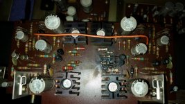
Thanks guys heres a pic of the initial damage. I replaced the output transistors on the right side and have not touched the left side. ive left the output transistors out of the left side while trying to get some decent results from the right side.
Ive replaced all of the caps and resistors that were bad on this damaged board. The diodes are still the old one as i dont know how to find out what they are without the schematic.
At this stage, when i turn it on there is no hum or anything, the main power supply all tests good - and + 39 volts. however if i put a signal into the input such as music, it comes out of the out put but weak and distorted when turned up there is no power in the sound at all it just drops off.
Hope it helps ill put more pics when i get home.
Attachments
just thought I would share a pic with this capacitor. It seems the capacitor has had its wrap shrink on it. It tests good but can a cap test good even though its bad?
I tested it on a cheap esr meter so i dont know if i can trust it especcially when this wrap has shrunk so much.
Any idea what this board is lol
I tested it on a cheap esr meter so i dont know if i can trust it especcially when this wrap has shrunk so much.
Any idea what this board is lol
Attachments
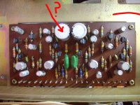
this board is the stereo preamp, each channel has 4 bipolar transistors (Gr) green a gain class indicator, and a junction fet marked Y. (and Idss class indicator).
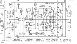
in the schematic one channel is in the dotted section central bottom, the other similar channel is above the potmeter section. above that in the left corner is probably the phono preamp stage, with 3 transistors/channel.
in the schematic one channel is in the dotted section central bottom, the other similar channel is above the potmeter section. above that in the left corner is probably the phono preamp stage, with 3 transistors/channel.
")
Just an observation, but that board has had repairs to both sides before.
The failure this time is Driver and SOA related. Several of those parts (transistor, diodes, resistors) have been previously replaced... If you have not already, replace Q312/314 and Q316/318 also D304/306 regardless.
With the board out, I would do resistance checks to compare all the caps and transistors from the 'good' side to the 'low' side. (Personally I would pull each transistor out to check it...)
Then with power on as avtech says in post 2, check DC offset Before attaching any speakers. I guess R312 (top right?) will give you a little adjustment if needed.
Then, again with no speakers, measure the voltage across either R12/14 (0.5R) and use ohms law to calculate idle current. R334 should give you a range of adjustment. No idea what the spec is, but 10mV will give 20mA to start with.
If they work as expected, then do comparative voltage checks round the transistors to find the fault.
Good Luck, all those 40 year old electrolytics...
Attachments
- Status
- This old topic is closed. If you want to reopen this topic, contact a moderator using the "Report Post" button.
- Home
- Amplifiers
- Solid State
- Who can help me fix this old amp :) low output