First post, breaking my lurker status!!
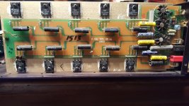
I thought I had the whole concept of 100ma of Iq per device by measuring the mV across the source resistors. What I didnt expect is there is a fair amount of difference across each of the resistors. This amp (Ada PF-2501) has 5 Buz90xP devices per half for a total of 10/ch. One channel idles a bit hotter than the other so I don`t believe the current bias settings are necessarily factory correct. Overall is runs cool...too cool.
I thought I could just adjust for 10mV across one of the 0.1ohm source resistors for a start and go from there....they will ALL be the same, right? NOPE.
On the Pch side I measured 8.3, 4.5, 5.1, 4.2, 3.7mV
On the Nch side I measured 5.2, 4.8, 5.9, 4.9, 5.0mV
So my Iq varies from 37ma to 83ma from device to device?
Weird coincidence (or maybe not) both sides total 25.8mV??
When I adjust the bias, all these voltages go up or down maintaining this deveation.
The other channel is just the same. Could this be normal for all batch#-matching lateral Fets? If so, how can you go about adjustment? Am I supposed to do some kind of averaging?
For whatever reason, they shunt each 0.1 ohm with 1/4w 4.7 ohm. Doubt that matters.
Just a little lost now.
Hi Sirpacsalot,
Congratulations on the first post")
An idle current deviation you're talking about is the normal thing as the output MOSFETs have got some variation of their Vgs parameter.
Bias circuit provides the same bias voltage to all the MOSFETs, however, their drain currents slightly vary just because of that natural Vgs deviation.
The way to make the current distribution between the MOSFETs more even is to match them by Vgs - say, take 50 pieces (well, at least 20, but the more is the better) of N-channel ones and select 5 pieces with Vgs close to each other. Then do the same with the P-channel ones, also trying to keep them as close to N-channel ones as possible in terms of Vgs.
I believe, MOSFETs in your Ada PF-2501 did not go through this process.
The fact that the N-channel and P-channel side currents sum up to the equal values is not a coincidence If they would not, you would not have zero DC offset at the output - that's the negative feedback, together with some trimming mechanism or a servo, make sure the offset is close to zero, then the total currents are automatically aligned between the N- and P- channel sides.
And finally - yes, the right way to set the bias in such a "mismatch-between-the-MOSFETS" situation - is to set the bias in a way that an average of idle currents is set to the target value.
Cheers,
Valery
Congratulations on the first post
An idle current deviation you're talking about is the normal thing as the output MOSFETs have got some variation of their Vgs parameter.
Bias circuit provides the same bias voltage to all the MOSFETs, however, their drain currents slightly vary just because of that natural Vgs deviation.
The way to make the current distribution between the MOSFETs more even is to match them by Vgs - say, take 50 pieces (well, at least 20, but the more is the better) of N-channel ones and select 5 pieces with Vgs close to each other. Then do the same with the P-channel ones, also trying to keep them as close to N-channel ones as possible in terms of Vgs.
I believe, MOSFETs in your Ada PF-2501 did not go through this process.
The fact that the N-channel and P-channel side currents sum up to the equal values is not a coincidence
If they would not, you would not have zero DC offset at the output - that's the negative feedback, together with some trimming mechanism or a servo, make sure the offset is close to zero, then the total currents are automatically aligned between the N- and P- channel sides.And finally - yes, the right way to set the bias in such a "mismatch-between-the-MOSFETS" situation - is to set the bias in a way that an average of idle currents is set to the target value.
Cheers,
Valery
More that 2:1 is a bit excessive I think. IME if I set a bias to 100mA and check the other emitter resistors, they’ll all agree to within 20-30%.
It may just be that you’re running bias a bit low - if you increase the bias a bit the temperature coefficient flips to negative, and they’ll share better.
It may just be that you’re running bias a bit low - if you increase the bias a bit the temperature coefficient flips to negative, and they’ll share better.
More that 2:1 is a bit excessive I think. IME if I set a bias to 100mA and check the other emitter resistors, they’ll all agree to within 20-30%.
It may just be that you’re running bias a bit low - if you increase the bias a bit the temperature coefficient flips to negative, and they’ll share better.
Quite often lateral mosfet's don't have source resistors.
Maplin did one in 1980's without source resistors from a Hitachi datasheet.
All Pch and Nch batch numbers match respectively.
So, you think best to pick a side, say Pch, raise Iq until the average of all 5 source resistors equals my target of 100mA? I wondered if I might see a change once I get to or beyond the temp coefficient.
And, yes the topology is exactly like the Maplin except using source resistors and a few silver micas here and there.
Attachments
You need to set the bias with output dc offset at as near zero as possible if you have a speaker connected.
If you disconnect the speaker before setting bias the two mosfets should have same bias.
This may be a bit... misleading.
It makes sense to set the offset and the bias (same applies to any other manipulations) with no speaker connected, for saving the speaker from any DC currents that may occur during the setup process at the times when the offset is not close to zero.
As soon as the bias is set and the offset is close to zero, it doesn't matter if the speaker is connected or not anymore, as with the offset close to zero the speaker is "neutral" - all the idle current goes from the "top" mosfets to the "bottom" ones, no current goes through the speaker.
Designs with no source resistors are possible (like Maplin), but they normally utilize a single pair of the output mosfets. As soon as you have 5 pairs of them, the source resistors are required for more even current distribution between the output transistors - exactly what we see here.
All Pch and Nch batch numbers match respectively.
So, you think best to pick a side, say Pch, raise Iq until the average of all 5 source resistors equals my target of 100mA? I wondered if I might see a change once I get to or beyond the temp coefficient.
And, yes the topology is exactly like the Maplin except using source resistors and a few silver micas here and there.
The other way of doing it - is setting the total idle current, say, 500mA for all the 5 output pairs. You can measure it, connecting the meter in series with one of the rails - doesn't matter which one of the two, as the total current, consumed from both rails will be equal. This method is somewhat... more dangerous, as you need to have a reliable connection at the meter leads, to make sure they don't fall off throughout the process.
Also, being precise, you need to know how much current is consumed by the rest of the circuit (IPS + VAS + driver stage if any) for adding it to the total, although it's going to be a rather small fraction (normally 10-20mA), comparing to that 500mA.
In any case - shorted input, disconnected speaker. First set the bias, then zero-out the offset.
I should have mentioned initialy that this design is force cooled by a low cfm fan. When the top and side is off for adjustments the fan does essentialy nothing. I let things come up temp, measure, average the different mV values, adjust, wait, repeat.
I managed to set an "average" bias of about 105mA only to watch it drop 15+ mA per device when i put the covers back on and the fan took effect....hmmff.
Sooo...under what thermal condition should I be making my measurements? This how I would do it for a confection cooled amp.
I managed to set an "average" bias of about 105mA only to watch it drop 15+ mA per device when i put the covers back on and the fan took effect....hmmff.
Sooo...under what thermal condition should I be making my measurements? This how I would do it for a confection cooled amp.
...This how I would do it for a confection cooled amp.
I love it. Marshmallows or ice-cream?
...under what thermal condition should I be making my measurements?
Probably the way you will be using it. Probably closed-up and, in this case, blowing?
Yes, things change. Just be glad it isn't one of the older sporty-cars where you had to take the valve-works all apart to shim, then put it all together to check your shimming. I suspect (and like the engines), one or two iterations will get you there.
- Status
- This old topic is closed. If you want to reopen this topic, contact a moderator using the "Report Post" button.
- Home
- Amplifiers
- Solid State
- Uneven bias with lateral mosfets