Ok, let’s speak about.
1. Your load is a speaker, so complex with intrinsic secondary power source and having a good phase lag.
2. Your OPS devices have huge Ft/Ic and beta/Ic dependance, you need to setup safe maximum Ic per device for keeping feedback loop stable and check driver stage load.
3. The most easy way to understand - is to see by yourself.
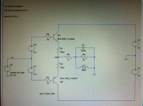
Simple OPS:

R3 is not clear, it must be taken from your woofer datasheet. Really there will be 5-6 Ohm for ~8 rated speaker and 2,7-3,2 Ohm for ~4 rated speaker.
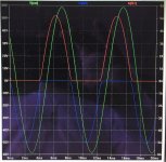
Simple sinewave above resonant frequency:

There are a good seen phase lag between output voltage and shoulders current.
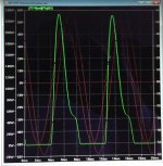
Now device dissipation:

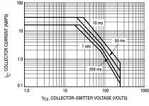
And datasheet SOA:

You can easily play with signal freq, supply voltage or load impedance and see the difference.
1. Your load is a speaker, so complex with intrinsic secondary power source and having a good phase lag.
2. Your OPS devices have huge Ft/Ic and beta/Ic dependance, you need to setup safe maximum Ic per device for keeping feedback loop stable and check driver stage load.
3. The most easy way to understand - is to see by yourself.
Simple OPS:

R3 is not clear, it must be taken from your woofer datasheet. Really there will be 5-6 Ohm for ~8 rated speaker and 2,7-3,2 Ohm for ~4 rated speaker.
Simple sinewave above resonant frequency:

There are a good seen phase lag between output voltage and shoulders current.
Now device dissipation:

And datasheet SOA:

You can easily play with signal freq, supply voltage or load impedance and see the difference.
OMG.
Say, up to 55-60 Volts supply and up to 6-7 A per package.
Stable work with 4-Ohm load not guaranteed.
High frequency inductive effect can be. But impedance is highly capacitive on one side of low frequency resonance, and highly inductive on the other. The higher the QMS value of the driver, the worse the phase angle. Reflex cabs, bandpass cabs, T-lines and horn loaders have more than one of these resonances to deal with. Each one capacitive on one side, inductive on the other. There tends to be more energy down there compared to up where a tweeter or midrange Le is dominating the impedance.
- Status
- This old topic is closed. If you want to reopen this topic, contact a moderator using the "Report Post" button.
- Home
- Amplifiers
- Solid State
- SOA BJT specialists wanted