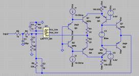
Simple and very effective common base concept.
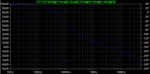
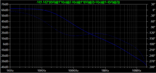
OLG plot for one of the possible compensation.
Inverting configuration with input filter.
2k input resistance for low noise.
Easy to put 10k linear potz before and pick ~100 dB logarithmic volume regulation.
Any high-GBW opamp like AD8067, LM7171 or LT1222.
Flexible loopgain tuning and shaping with depth up to 120 dB at 20 kHz.
Common base V/I converter (or level shifter for easy of understanding).
Common base I/V converter (as we like - VAS).
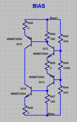
Any preferable Bias spreader.
Any preferable OPS.
OLG plot for one of the possible compensation.
Inverting configuration with input filter.
2k input resistance for low noise.
Easy to put 10k linear potz before and pick ~100 dB logarithmic volume regulation.
Any high-GBW opamp like AD8067, LM7171 or LT1222.
Flexible loopgain tuning and shaping with depth up to 120 dB at 20 kHz.
Common base V/I converter (or level shifter for easy of understanding).
Common base I/V converter (as we like - VAS).
Any preferable Bias spreader.
Any preferable OPS.
Attachments
Hi Pavel,
I like the approach. In fact, the input stage may not necessarily be an op-amp - it may be something relatively low-gain (but still rather linear).
Common base structures make a lot of sense, providing "current driven" amplification (wide bandwidth / low phase shift).
Worth further development / prototyping 😉
Cheers,
Valery
Interesting
I like the approach.
Thank you guys. Let's discuss bias and OPS!
In fact, the input stage may not necessarily be an op-amp
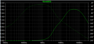
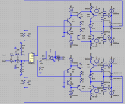
Yes, of course. It's easy like 2x2, attached SCH+OLG+ONoise+Output resistance.
Common base structures make a lot of sense, providing "current driven" amplification
Free from Cob and because of this - good isolation between hi-voltage out and low-voltage in.
Attachments


It looks nice, I did something which is closely related to this solution. Anyway I will try Your version too..
Sajti
Sajti
I did something which is closely related to this solution.
Yeah, there are nothing new, let me not to invent a bike again.
The main idea is to effectively use high-GBW opamp (with intrinsic pole at least upper than audioband).
Frequency correction structure allow us to use ordinary nominals and not have a huge noise gain at UGF.
Let’s vote for OPS.
Common EF-triple or dynamically cascoded SF-one?
dynamically cascoded SF-one?
What ab this?
R.15-R.22 at OPS sources.
Attachments
In their 1978 datasheet for their BD550 family of power transistors, RCA published something very similar to the circuitry shown in #1 as an application in a 300 watts amplifier. The opamp at the input was a CA3100 (now obsolete since decades), fed from +/- 15 V. Main power supply rails were +/- 90 V. RCA called this circuitry of four transistors a level translator.
Best regards!
Best regards!
If you google up Analog Devices AN-211 you will find a power amp based on your ideas. I might add that my QRV03 headphone amp is based on AN-211.
RCA published something very similar
Yeah, right!
But they drive first common base stage from 1,5 kOhm resistance, so say killed this stage gain. Second stage are fed from BE junction, so Cob doesn’t effectively cancelled. Opamp have local feedback loop, so doesn’t help at HF in global loop.

If you google up Analog Devices AN-211 you will find a power amp based on your ideas.
I have found ADI AN-211, but can’t see something similar.

Last edited:
Opamp have local feedback loop, so doesn’t help at HF in global loop.
View attachment 681644
Yes, that's exactly the amplifier design I've meant 😉!
I don't see any local feedback around the CA3100, There's just a small compensation capacitor from it's output to the inverting input and another one for internal compensation.
The BD550 datasheet from 1978 shows some more application for these power transistors, mostly basing on the - no surprise - RCA Transistor Manual from the early 1970ies. Also included were explanations of each schematic.
Btw, did these BD550's ever see the light of the market?
Best regards!
Last edited:
small compensation capacitor from it's output to the inverting input
Yes. It drops opamp gain at HF(need to say, that there are not so much), so feedback depth will be lower and high-order THD raises. You know for what they are responsible.
- Status
- Not open for further replies.
- Home
- Amplifiers
- Solid State
- Opamp + Common base