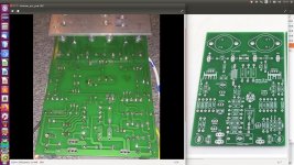
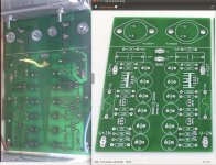
I made a photo of the bottom sides of the pcb's and mirrored them. This way I could compare it with the top sides. On jhte pwr boards I found that (TR2 and TR4 had to be rotated 180 degrees. Fotr the amp board I found that the 680 Ohm and 390 Ohm resistors in the base of TR8 had to be swapped. 
Attachments
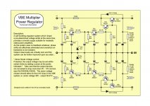
On the far right of the regulator board schematic are two pairs of 4K7 1 watt resistors. These are the bleeders that are supposed to bring the PSU down gracefully when you power off. Check to see if they're the same value.
It's also possible you damaged one of the other transistors when the 2N5401s blew. What was the fault that caused that?
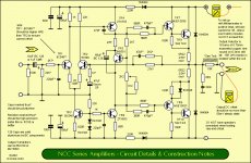
You mentioned you changed one of the Zeners. Do you have two in series for each one shown on the schematic? If not, and you changed the Zener on the negative rail but not the positive rail (or vice versa) that's going to unbalance the whole amp.
It's also possible you damaged one of the other transistors when the 2N5401s blew. What was the fault that caused that?
You mentioned you changed one of the Zeners. Do you have two in series for each one shown on the schematic? If not, and you changed the Zener on the negative rail but not the positive rail (or vice versa) that's going to unbalance the whole amp.
I measured the resistance of the bleeders: both 2.4KOhm which is consistent with two 4k7 in parallel.
The blowout was caused by connecting an actual loudspeaker to the output of the amp in stead of a 6 ohm resistor. (All measured values above where done without a load, but the resistor did not change bias or offset). I do npt remember anymore if the blowout was at switch off or before that. If I replace the fuses on the power supply with a current meter I see a current flowing that is the sum of the bias current and that through the two 4k7 resistors. Because of that I think the MJxxx transistors had survived
For the positive side of the power supply I now have a 16 Volt zener in series of a 27 Volt.
The same thing is true for the negative side. The supply voltage to the amp is now +/- 41.5 Volt.
Just a thought: is my problem caused because TR2 stops conducting way before TR1 does so there is no more feedback to keep steer the output value to zero? If so what can be the cause?
Another thing I did not mention I used a 4Euro multimeter to measure the hfe of TR1 and TR2. Tr1 had, if I remember it well, a hfe of 605 and the other of 530.
Another thing I did not mention I used a 4Euro multimeter to measure the hfe of TR1 and TR2. Tr1 had, if I remember it well, a hfe of 605 and the other of 530.
hFE of TR1 and TR2 won't matter -- that would only change the steady-state offset, not the offset during power down.
The feedback doesn't directly affect the offset either -- it only attempts to zero out the AC error. A DC servo is used to zero out the offset, but the Naim circuit doesn't use one.
When measuring the regulator output without the amp attached you're seeing an unbalance when powering down, right? Whichever rail goes down faster may have a blown capacitor on it....
little more testing
Did some more testing, but to no avail unfortunately. I tried the other power supply and the other amp board. Shutdown behavior was problematic in all cases. Then I tried with just a dual transformer, dual rectifier and two electrolytics together with two bleeders of 2k4. This gave me a +/- 26Volt power supply. When I switched it off I see the same problem as with the power supply boards: offset slowly climbing to several volts. I therefore think that both my amp boards have the same error.
When I started with setting the offset, I did not have a connection between the ground of my out put and the ground of the input of the amp. (The board does not have these all connected) This caused a very high negative offset of almost -Vcc. I had this with both boards. Adding a wire to the board connecting the ground connections made it behave. Except of the problem that I still have of course.
What to do? If anyone can help me further I'd be very thankful.
Start at the beginning. You may have assumed that the Avondale circuit you are following and the Aliexpress clone PCB are compatible but by your own comments, they cannot be. Have you looked at the schematics closely and compared them? Consider; are your semis genuine or known good equivalents? Are the raw DC supply voltages within 3-5 volts of the required output voltage of no more than say, 42V?
I assume that you can't test capacitors with your 4 euro meter but if you want to play with circuits and change designs to suit available parts, you need good test equipment to verify that your components and your finished gear is good to go. Unfortunately, basic hobby electronics stuff just isn't enough. There are cheap, all-in-one testers out there but their capabilities are usually limited to small capacitors.
Perhaps you have already compared the full schematics and made all necessary corrections but I would not confuse the two designs as if they were the same nor would I presume that the regulators should behave like any feedback controlled device. As Jeff pointed out, there is no feedback so the input voltage of the supply has to be within a small range of the output which will settle according to capacitor time constants and the load, when powered on/off. You should expect a significant settling time according to capacitor sizes so don't oversize them. If both channels are powered simultaneously when a load is connected to the amplifiers, you should find that settling and decay times are somewhat reduced.
Last edited:
- Status
- This old topic is closed. If you want to reopen this topic, contact a moderator using the "Report Post" button.
- Home
- Amplifiers
- Solid State
- naim clone pcb's