Hi All
I have one of these amps which I got for free but has 4 visibly blown resistors and will not power on. Blows fuses instantly. I want to learn how to repair it. I can solder and know some very basic electronics, etc but do not really understand a schematic. I do have a digital multimenter and know how to set the bias and check the DC. It has no IC's, all discrete components.
I have the other one of the pair which works fine so I have a working double to compare with.
Would anybody be willing to take me step by step in trying to fix this? I accept all liability for loss or damage!
Will provide pics of burnt resistors, more info, etc as required. I am happy to take my time as I am really keen to learn and have nothing to lose so to speak.
Let me know your thoughts
Last edited:
Yes the large white 0.22 ohm resistor and what looks like 3 small resistors just to the right of it which are in parallel to it.


Ouch. Definitely failed output transistors, and probably failed driver transistors as well.
Check those 0.22 ohm resistors, they may actually be OK. If they read open circuit on your multimeter, you will need to replace them.
Next clean up the big burned mess.. you should find this is resistors R635 and R633. Remove them from the board and clean up using isopropyl alcohol. Hopefully the board itself is not badly burned.
Next, remove the 4 power transistors, Q627, Q629, Q631, Q633. Test those using the diode check function of your multimeter. See here for how to do this:
Test a transistor with a multimeter.
Next, remove the 2 smaller transistors that were next to the power transistors. These are the driver transistors Q623, Q625. Test them in the same way.
Report back with the results of these tests.
Edit: The schematic for the unit is here: ROTEL RB970BX Service Manual download, schematics, eeprom, repair info for electronics experts
That’s great. Really appreciate this. Will make a start tomorrow and post when I have made some progress.
Hi. Just had a quick look - will not have time to actually do anything today....... but, what is the best way to dismantle the case as Q631 does not coincide with the openable back? I will only check the "burned" left hand side of the amp for now. Is this correct.
That looks pretty horrible. If all these three 0,25W resistors are burned (R629, 633 and 635) , you should check all semiconductors in that channel. not only the output stage, also the predriver and driver stage. Let's hope that all semiconductors are still available from trustworthy resources.
For more details you can also check at Login - HiFi Engine.
Register for free and download the service manual
Lots of success and BR
Günni
For more details you can also check at Login - HiFi Engine.
Register for free and download the service manual
Lots of success and BR
Günni
I get the feeling that only R635 will be fried due to current through it, the other two will have been fried due to their proximity to R635. I've not serviced one of these amps before, but have serviced similar Rotels and usually it's the outputs + drivers that go... the predrivers tend to survive.
The exact replacement parts are not available any more. I used KSC2690/KSA1220 to replace the driver transistors, and NJW0281/NJW0302 to replace the outputs on a similar Rotel amp.
The exact replacement parts are not available any more. I used KSC2690/KSA1220 to replace the driver transistors, and NJW0281/NJW0302 to replace the outputs on a similar Rotel amp.
Hi. Some results. I can only do it in stages as have to drop my son off and pick up for various sports events.
I removed one leg and tested 3/ 4 easily accessible 0.22 ohm resistors. All read 0.5 - 0.6 ohms. I tried the other side as well but without removing the resistors and they read the same after settling down
On closer inspection all 3 driver transistors are burned. Removed Q625 only so far and appears out of spec
BE 0.130v
BC 0.007v
EB 0.106v
CB 0.007v
CE 0.280v
May as well replace all three. Of NJW0281/NJW0302, which is best? Both available from RS at around 30 pence each - min 10. Do I need to replace the other side as well?
The power transistors 2SB817 (ON) and 2SD1047 (STM) are still available at Mouser, Also the KSA1220A and KSC2690A, so it shouldn#t be a problem to fix the amp.
For me the 0.22R looks ok, the dark sign should come from the hot spot , when the resistor and the pcb burned.
For me the 0.22R looks ok, the dark sign should come from the hot spot , when the resistor and the pcb burned.
Last edited:
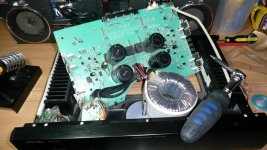
Although the surface of the circuit board is burnt the tracks behind it appear ok although slightly lifted. Not had time to test any more transistors tests (can only desolder in the cold garage!) but found all the potential parts I may need including transistors for both sides (if needed) for £33 from Mouser. Just keeping it all in the basket for now until I have time to do more of the tests.
Last edited:
You should substitute the parts as follows
KSC2690 - substitute for 2SD600 driver transistor
KSA1220 - substitute for 2SB631 driver transistor
NJW0281 - substitute for 2SD1047 output transistor
NJW0302 - substitute for 2SB817 output transistor
I did see that the 2SD1047 and 2SB817 are made, but as they are not made in complimentary pairs by the same manufacturer, i wouldn't use them. The NJW0281/0302 are good output transistors with very similar characteristics to the originals, and should perform perfectly well in this circuit.
It sounds as if the 0.22 ohm emitter resistors are fine, and I wouldn't bother changing them. You should replace R629, R633, R635 even if they measure OK, as they have obviously been severely damaged by the overload.
Thanks for all the advice so far. I will not have time to do more until the weekend. Will post again when I have made further progress.
Hi all. Minor update. Only part of the rear of the amp is removable which makes it difficult to access some of the transistors. I have therefore removed the circuit board although it is still attatched to the power supply. I have torn some of the paper backing on the transistors while removing them from the heat sink. Does this matter and will the new transistors come with new bits of paper backing?
Showing my ignorance here!
Should I be testing the smaller transistors on the board as well or am I going too far?
I have found matched pairs for the larger power transistors at RS componenets. Is it worth just replacing the lot for both sides if only one side is faulty? (Not removed and tested yet).
Attachments
Last edited:
Leave the other channel alone if it is not faulty. It may prove useful if you have further problems, since as you will have a working channel to compare to.
The "paper backing" are not paper, they are thermally conductive insulator pads. The new transistors will not come with them. if you have damaged them, you will need replacements. Farnell part number 936753 for the output transistors, and 936741 for the driver transistors. You MUST have these insulators in place or you will create a short circuit.
At this point I would not bother testing the small signal transistors.
Thanks for that Jaycee. I worked it out later! I thought I just needed thermal grease. It is the first time I have attempted to change a transistor on a heatsink. The learning curve continues.
What does matched pairs of transistors mean?
Another newbie question. Does "matched pair of transistors" refer to within the same channel or matched between the channels. So do I match Q631 with Q627 on the left channel or match Q631 with Q632 on the opposite side?
The amp has 4 transistors per channel (2 different types).
Another newbie question. Does "matched pair of transistors" refer to within the same channel or matched between the channels. So do I match Q631 with Q627 on the left channel or match Q631 with Q632 on the opposite side?
The amp has 4 transistors per channel (2 different types).
Last edited:
Another newbie question. Does "matched pair of transistors" refer to within the same channel or matched between the channels. So do I match Q631 with Q627 on the left channel or match Q631 with Q632 on the opposite side?
The amp has 4 transistors per channel (2 different types).
Hi ssi,
the first assumption is correct, matching the 2 NPN Q631 and Q627 semiconductors and the same for the 2 PNP Q629 and Q633, alltimes pairwise. Matching between PNP and NPN is usually very cost- and time-intensive. You will see, when you measure the parameters of the transistors, that 10% difference (between 2 PNPs or NPNs) is good enough.
Hi Jaycee,
there is no matching required for the power transistors, since during production no matching was made. If the measurement tools are available, it's always good checking the parameters. Furthermore i only would repair the defect channel and use the working channel as reference, and possible in a second step change the power transistors in the working channel. just an idea?? or leave it as it is, when you are not sure in handling.
there is no matching required for the power transistors, since during production no matching was made. If the measurement tools are available, it's always good checking the parameters. Furthermore i only would repair the defect channel and use the working channel as reference, and possible in a second step change the power transistors in the working channel. just an idea?? or leave it as it is, when you are not sure in handling.
- Status
- Not open for further replies.
- Home
- Amplifiers
- Solid State
- Rotel 970 BX Repair