.....one half is running hotter than the other.
Idle current (heat) is fixed by diodes, Q1 Q2, and the 5R1 resistors. Should be SAME voltage at Base of both Q1 and Q2. Both "5R1" should really be about 5 Ohms and not too different from each other (10%). Find out what is different across the two channels.
.....There are two variable resistors which I measured were both set half way.
Trimmers VR3 VR4 set the output DC. Unlike many newer amps that naturally tend to give less than 0.1V output DC, this one balances a roughly 2V (and variable) offset in Q5 Q6 and resistors against an offset dialed-in with the trimmers. You should easily be able to get output DC to much less than a Volt. Even a Volt will cause some excess heat in both the amplifier and the headphones. Try to get it less. However there are temperature effects in both the Vbes and the hFEs, so it may never hold output DC to less than 0.1V.
For anybody following at home: this plan runs 120mA idle, 230mA peak, maybe 11V peak, so is optimized for about 44 Ohm load, so over 1 Watt into typical 32-50 Ohm headphones, and very ample even for 600-2K phones.
Idle current (heat) is fixed by diodes, Q1 Q2, and the 5R1 resistors. Should be SAME voltage at Base of both Q1 and Q2. Both "5R1" should really be about 5 Ohms and not too different from each other (10%). Find out what is different across the two channels.
Trimmers VR3 VR4 set the output DC. Unlike many newer amps that naturally tend to give less than 0.1V output DC, this one balances a roughly 2V (and variable) offset in Q5 Q6 and resistors against an offset dialed-in with the trimmers. You should easily be able to get output DC to much less than a Volt. Even a Volt will cause some excess heat in both the amplifier and the headphones. Try to get it less. However there are temperature effects in both the Vbes and the hFEs, so it may never hold output DC to less than 0.1V.
For anybody following at home: this plan runs 120mA idle, 230mA peak, maybe 11V peak, so is optimized for about 44 Ohm load, so over 1 Watt into typical 32-50 Ohm headphones, and very ample even for 600-2K phones.
Sage advice on setting the dc offset - however the problem of heating the headphone voice coils would be more of a concern if these are 8 ohm types and less critical with high impedance types.
I agree that long tail pair inputs usual in op.amp structures have more stable dc characteristics. I note the 2N2907 transistors are quite close to some heat sinks - there would be less inclination for these to affect drift if these were not allowed to be affected by heat. Some form of heat sink - like a small piece of aluminium could be glued to the flat face. The value of the resistor I suggested changing from 2k2 to 3k3 does have an effect on the standing current. Once it is turned on by the diodes a parallel resistor diode path is created via the emitter base junction of the 2N2907's and the current so passed depends on the resistance through this path. Less resistance means more base current and greater conduction.
The output devices now are TIP41 formerly 2N4922 so the value will depend on the gain characteristics of the transistors involved. There may be some variability in the current draw between the channels using the same value resistors so trimming for a match might be a matter of devising a suitable combination of resistors in series or parallel. Fingers crossed there is a reasonable match.
Last edited:
It's rather note to self. Will think and analyse later.
Resistor, ohms measured, voltage drop
(hot channel / cold channel)
R1,2 5R2/5R2 0.446V/0.664V
R3,4 4K69/4K66 0.31V/0.76V
R9,10 2K18/2K20 10.83V/10.83V
D1,2,3,4 all show same voltage drop of around 0.6V.
Rail Voltage on caps: 12.26V -11.99V
Could the difference in heat on left/right power transistors be caused by assimmetric rail voltage?
...R3,4 4K69/4K66 0.31V/0.76V...
Q2 should be flowing 0.6V/100r (R26) or 6mA. The drop in R4 says 0.16mA base current. 6mA/0.16mA says Q2 has hFE of 37..... we expect >100.
But epicyclic says the voltages are just wrong (I didn't check), and a short is indeed a likely fault.
I'm so so new... ") I will try to interpret your messages... The numbers are the actual reading of the multimeter, and not because I expected any numbers. If they don't make sense it's because either error of measuring or of interpreting the diagram to match the real board I'm dealing with. Also, I can't fault the amp simply by listening - it sounds alright, both channels, so a "short" is just unlikely. More likely human error.p measuring.
I will try to interpret your messages... The numbers are the actual reading of the multimeter, and not because I expected any numbers. If they don't make sense it's because either error of measuring or of interpreting the diagram to match the real board I'm dealing with. Also, I can't fault the amp simply by listening - it sounds alright, both channels, so a "short" is just unlikely. More likely human error.p measuring.
I will try to interpret your messages... The numbers are the actual reading of the multimeter, and not because I expected any numbers. If they don't make sense it's because either error of measuring or of interpreting the diagram to match the real board I'm dealing with. Also, I can't fault the amp simply by listening - it sounds alright, both channels, so a "short" is just unlikely. More likely human error.p measuring.... The numbers are the actual reading of the multimeter, and not because I expected any numbers. If they don't make sense it's because either error of measuring or of interpreting the diagram to match the real board I'm dealing with. Also, I can't fault the amp simply by listening - it sounds alright, both channels, so a "short" is just unlikely. More likely human error.p measuring.
Nobody seems to question your measurements. YOU said "However one half is running hotter than the other." Those readings also say the two channels are working very differently. Maybe a 2:1 difference of current. A mis-wire or a short would be a likely possibility; not all shorts burn down the house. A bad part is possible but very unlikely.
One side is putting out more DC in to the speaker and so generating more heat.
If the DC offset is wrong you can get one output transistor being hotter than the other.
I usually use constant current sources so amp is more stable.
I also use a VBE multiplier to control bias.
If the DC offset is wrong you can get one output transistor being hotter than the other.
I usually use constant current sources so amp is more stable.
I also use a VBE multiplier to control bias.
Hi all first poster here,
I figured I post my question here, since this seems to be the most active thread on the ZeroZone JLH1969. I recently got several of the kits off ebay and i was wondering about the designated spots to "jump" the PCB.
OP has not soldered connections in these, but I have seen pictures with and without them on the net. Could anybody shed some light on this?
I do not fully understand the schematics and I am wondering whether i should jump them.
Cheers
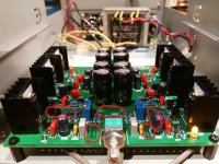
If you look at any pic of the assembled PCB, you'll see 3 green connector blocks. One has 3 connection screws and is labelled AC-0-AC for the 12V transformer connections, 2 similar blocks have only 2 connection screws and these are for the headphone R & L channel outputs and their common earth connections.
The last connector is different. It's a flat ribbon cable type for the stereo signal input cable. This type of cable is used because the signal wires are sensitive to hum and noise so shielding of some type is essential and it's reasonably effective. There are also printed letters on the PCB alongside each block, which indicate the purpose of each connection to it. This is your guide to making connections, but also refer to the schematic so that you understand each connection's function and the corresponding leads are correctly identified and routed to their terminals/sockets etc.
Take care that you understand the above, since you don't want to create shorts that damage your amplifier. Perhaps you could also minimise possible damage by connecting and testing only one channel before proceeding with the the other.
There may be differences in kits with some suppliers so use a little thought when reading this. Assembly may be tedious but its not difficult, regardless of language differences, if you follow schematics and read polarities correctly, rather than guess or rely too much on visual aids
Last edited:
Thanks for the quick reply.
I'm sorry my question was badly worded. I am particularly interested in the effect of jumping the connections I have marked in OPs picture attatched.
My boards came already assembled from ebay, so I guess like OP I am assuming that they are fully assembled. I have, however, seen boards with these connections jumped. (In real life (sounded fine) and also on ebay: https://i.ebayimg.com/images/g/S8IAAOSwAYtWLan~/s-l1600.jpg
So I'm wondering what the effect of jumping those designated connections would have and whether I should jump them.
Any help is greatly appreciated!
Cheers
Attachments
- Status
- This old topic is closed. If you want to reopen this topic, contact a moderator using the "Report Post" button.
- Home
- Amplifiers
- Solid State
- DIY JHL1969 newbie question