Oops, I'm too slow -- 'Mooly' beat me to it ..
Not that my two-cents is any more valuable than these other fine folks ... but I agree
with posts #16, 18, and 19 -- "Follow the Wires" -- (say it while you think of 'All The President's Men'). There's little likelihood that the part is involved in bias of any sort, since it would be extremely complicated -- and foolish -- to try to bias two separate output stages with one temperature sensor. It all but HAS to be a 'catastrophic overtemp protect' sensor, which I'll dredge the schematics for again, now that I'm not looking for a component involved in bias-setting.
Regards, --Rick
I have a theory.
The NAD seems to use series FET switches to mute the pre out section. Could the thermistor act on those to mute or soft mute the audio when things get to hot.
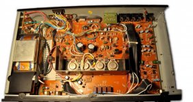
I can't see a thermistor on the poor diagrams I can find on the web but I did find a picture showing the thermistor and it looks to go to the small signal circuitry.
The NAD seems to use series FET switches to mute the pre out section. Could the thermistor act on those to mute or soft mute the audio when things get to hot.
I can't see a thermistor on the poor diagrams I can find on the web but I did find a picture showing the thermistor and it looks to go to the small signal circuitry.
Attachments
I'll trace out where the extra components are connected to.
Thanks for all the help - It's always heartening to find a knowledgable bunch of people on a forum! 🙂
Thanks for all the help - It's always heartening to find a knowledgable bunch of people on a forum! 🙂
Mooly,
The theory sounds good. The pic you posted shows it -- the leads go right to the tone pot area of the board, which is electrically next to the mute FETs. We're gonna need some better board prints. I've scoured the posted ones and can't find any sign of the thermistor, either.
--Rick
The theory sounds good. The pic you posted shows it -- the leads go right to the tone pot area of the board, which is electrically next to the mute FETs. We're gonna need some better board prints. I've scoured the posted ones and can't find any sign of the thermistor, either.
--Rick
Thanks 🙂
If this is all it does then it will be a case of either leaving it removed or shorting it out with the proviso that we really should see the details before shorting. If it comes down to being 'not open' for normal operation and if we have no details then I would suggest trying ever decreasing fixed resistors, 100k, 47k, 10k 1k etc and see at what point things work normally. Then just fit something significantly lower than the one at which it starts to work and it should be good to go.
If this is all it does then it will be a case of either leaving it removed or shorting it out with the proviso that we really should see the details before shorting. If it comes down to being 'not open' for normal operation and if we have no details then I would suggest trying ever decreasing fixed resistors, 100k, 47k, 10k 1k etc and see at what point things work normally. Then just fit something significantly lower than the one at which it starts to work and it should be good to go.
It does 'work' shorted out - I tried this when I thought it was a fuse - oops. Trying to do a diagram just now and figure out what is on this board that isn't on the available diagrams. Any recommended circuit diagram drawing tools?
Pencil and paper is as quick as anything for making quick notes 😉 or windows paint.
Right, if it works when shorted then you could simple add something like a 100 ohm in its place and then measure the DC voltage across the 100 ohm. Anything below 0.5 volt or so means the current is minimal (<5ma) and shorting should be OK.
Right, if it works when shorted then you could simple add something like a 100 ohm in its place and then measure the DC voltage across the 100 ohm. Anything below 0.5 volt or so means the current is minimal (<5ma) and shorting should be OK.
I doubt anyone could decipher my diagrams 🙂 Got to go just now - will post later.
Oh - the postie had just delivered the big transistors - but that's another thread...
Oh - the postie had just delivered the big transistors - but that's another thread...
No, just an example.Like this you now a type number of a part like that.Any particular reason for that exact one?
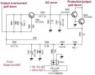
RS makes an error here. According to Murata the 471 in the part number indicate a 470Ω resistor where RS says 100Ω 😱
Here a schematic where a PTC is used.
Mona
Attachments
bigshuggy,
Since even casually scribbling a schematic can burn up a lot of time, AND pencil eraser, maybe you could just list the 2, or 3, or 4 parts (R602, D601, etc) that each wire connects to, like:
white wire=xxxx, xxxx, . . .
yellow wire= . . .
Then we could try to sort out which part somebody forgot to draw the little dashed-line bracket around -- and/or mislabeled.
When you have time to get back to it, of course . . .
--Rick
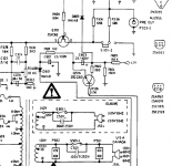
The 7020I has a thermistor in the muting circuit. The 7020I is essentially the 3020I with a tuner. The thermistor is directly above the AC power plug on the right side of the schematic.
Craig
Craig
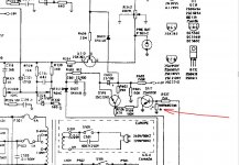
this as far as I've got - hope it's of some use. Apologies if images too big for the forum.
Q516 is that last know quantity form the common schematic so thought that might be a good starting point? Transistor symbols are not accurate - just used for pins...
Q516 is that last know quantity form the common schematic so thought that might be a good starting point? Transistor symbols are not accurate - just used for pins...
An externally hosted image should be here but it was not working when we last tested it.
An externally hosted image should be here but it was not working when we last tested it.
An externally hosted image should be here but it was not working when we last tested it.
Last edited:
Well done 
The thermistor appears to turn off (gradually as its resistance falls) Q517. Assuming the 7020i is the same as yours then Q517 is a PNP device (note how the arrow on the emitter points inward).
The thermistor appears to turn off (gradually as its resistance falls) Q517. Assuming the 7020i is the same as yours then Q517 is a PNP device (note how the arrow on the emitter points inward).
Well done
The thermistor appears to turn off (gradually as its resistance falls) Q517. Assuming the 7020i is the same as yours then Q517 is a PNP device (note how the arrow on the emitter points inward).
I knew someone would pick me up on the symbol I used 😀
So - what's the general consensus? Short it and see how it goes? Is the thermistor essentially just acting as a temperature switch then?
I think when the amp/ heatsink gets too hot it mutes the signal until it can cool off to a safe temp. If you short across the thermistor I think it will be stuck in mute forever. This is assuming an NTC thermistor, one that decreases resistance with rising temperature.
Craig
Craig
- Status
- Not open for further replies.
- Home
- Amplifiers
- Solid State
- NAD 3020i thermistor? Has anyone even seen this before?