Hi there,
Some times ago, I presented a tentative "Smart Fuse" for speakers:
http://www.diyaudio.com/forums/solid-state/255609-s-p-autonomous-speaker-protection-system.html
It was an exploratory, proof-of concept project, and although it did work, it had some issues, the main one being the current consumption, making it unpractical to use.
I have now solved these issues, and the version 2 is fully mature -and I am going to use it-
The excessive consumption of the version 1 was caused by the CMOS Schmitt trigger having its inputs biased in the linear region.
I therefore abandoned this solution, and at that stage, I had two options: use micropower circuits, comparators, opamps, regulators, etc. or opt for a completely discrete circuit.
I hesitated for a long time, but in the end I opted for the discrete path: there are plenty of micropower circuits around, but, they are mostly specialty circuits, specific to each manufacturer, generally not interchangeable or having alternate sources available, something I don't like very much.
The discrete circuit is significantly more complex, but it has excellent perfomances, can be built with commodity components and is extremely versatile and flexible.
The detection engine has remained the same, but all the rest has been modified.
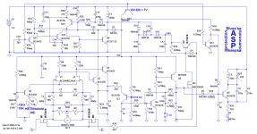
The main innovation is the use of a power converter to generate the supply voltages.
The quiescent consumption of the whole circuit is ~175µA, thus apparently not an improvement over v1, except of course that this current is drawn from a single cell, which makes a huge difference: the capacity is much larger, and the power density is also improved compared to a multi-cell battery.
The converter is built around Q9 to Q12, and does not require custom magnetics: an ordinary, two-terminal choke is sufficient.
It is messy and and complex, but it is worth the trouble: it works from 0.85V to several volts, is regulated, has an efficiency of 80~90%, even at low output currents, and its no-load consumption is only a few microamps.
It generates the 8V used by most of the circuit, and the 16V for the gates drive, via a voltage doubler (a tripler actually, because of the very asymmetric nature of the waveform).
The trip indicator is now acoustic: a LED couldn't be driven directly from the cell, and connecting it to the converter would waste lots of power.
The buzzer driver is a single transistor oscillator, operating in "squegging" mode, to generate short tweets every two seconds.
It is very effective, providing more than 5Vpp to the piezo with a 1.5V supply, consuming only a few hundred of µA's.
Thus, even in the trip mode, the consumption remains well below 1mA.
The sound generated doesn't sound loud, because of the soft envelope of the bursts, but it is surprisingly audible: I can easily hear it over the 4 levels of my house.
It also serves as a low battery indicator, when the converter begins to loose the regulation.
The characteristics of the fuse can be tailored for any behavior: R19 sets the overall caliber, C1, C3, C4 and R6 to R8 dictate the frequency/DC sensitivity, while C2, C5, R21, R22 determine the temporal behavior.
The exact tripping threshold can be adjusted in several ways.
Although it will work on a AA battery (and last about 1.5 yr), I recommend a C or D size cell: the life will be practically the shelf-life.
Some times ago, I presented a tentative "Smart Fuse" for speakers:
http://www.diyaudio.com/forums/solid-state/255609-s-p-autonomous-speaker-protection-system.html
It was an exploratory, proof-of concept project, and although it did work, it had some issues, the main one being the current consumption, making it unpractical to use.
I have now solved these issues, and the version 2 is fully mature -and I am going to use it-
The excessive consumption of the version 1 was caused by the CMOS Schmitt trigger having its inputs biased in the linear region.
I therefore abandoned this solution, and at that stage, I had two options: use micropower circuits, comparators, opamps, regulators, etc. or opt for a completely discrete circuit.
I hesitated for a long time, but in the end I opted for the discrete path: there are plenty of micropower circuits around, but, they are mostly specialty circuits, specific to each manufacturer, generally not interchangeable or having alternate sources available, something I don't like very much.
The discrete circuit is significantly more complex, but it has excellent perfomances, can be built with commodity components and is extremely versatile and flexible.
The detection engine has remained the same, but all the rest has been modified.
The main innovation is the use of a power converter to generate the supply voltages.
The quiescent consumption of the whole circuit is ~175µA, thus apparently not an improvement over v1, except of course that this current is drawn from a single cell, which makes a huge difference: the capacity is much larger, and the power density is also improved compared to a multi-cell battery.
The converter is built around Q9 to Q12, and does not require custom magnetics: an ordinary, two-terminal choke is sufficient.
It is messy and and complex, but it is worth the trouble: it works from 0.85V to several volts, is regulated, has an efficiency of 80~90%, even at low output currents, and its no-load consumption is only a few microamps.
It generates the 8V used by most of the circuit, and the 16V for the gates drive, via a voltage doubler (a tripler actually, because of the very asymmetric nature of the waveform).
The trip indicator is now acoustic: a LED couldn't be driven directly from the cell, and connecting it to the converter would waste lots of power.
The buzzer driver is a single transistor oscillator, operating in "squegging" mode, to generate short tweets every two seconds.
It is very effective, providing more than 5Vpp to the piezo with a 1.5V supply, consuming only a few hundred of µA's.
Thus, even in the trip mode, the consumption remains well below 1mA.
The sound generated doesn't sound loud, because of the soft envelope of the bursts, but it is surprisingly audible: I can easily hear it over the 4 levels of my house.
It also serves as a low battery indicator, when the converter begins to loose the regulation.
The characteristics of the fuse can be tailored for any behavior: R19 sets the overall caliber, C1, C3, C4 and R6 to R8 dictate the frequency/DC sensitivity, while C2, C5, R21, R22 determine the temporal behavior.
The exact tripping threshold can be adjusted in several ways.
Although it will work on a AA battery (and last about 1.5 yr), I recommend a C or D size cell: the life will be practically the shelf-life.
Attachments
Last edited:
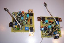
Here are some pics of my build.
With the values I have chosen, the tripping threshold for a permanent DC current is ~0.8A with the trimmer centered; the range extends from less than 0.5A to more than 2.5A.
At higher frequencies, the sensitivity becomes progressively lower thanks to the filter.
The time constants I have chosen are a bit short, verging on paranoiac, but this can easily be changed.
I do not need to listen at high volumes, and if a high current is detected, I don't mind having a quick reaction....
Attachments

Amusing but what is the use of a batt for protecton ? I would say, if there is no voltage there is nothing to protect, if there is use it.
And is Q14 in the wrong direction or do i miss something ?
Mona
And is Q14 in the wrong direction or do i miss something ?
Mona
The idea is to build the system into the speaker itself: that way, even if the amplifier ends in a total disaster, the speaker will be protected and safe.Amusing but what is the use of a batt for protecton ? I would say, if there is no voltage there is nothing to protect, if there is use it.
Also, if you connect an unsuitable or unknown amp to your speakers (say a 500W amp on 60W speakers), the limit will be set by the speakers themselves, not the amplifier.
Of course, it wouldn't be practical to have a kind of half-assed active speaker, with a mains connection, and an ON/OFF switch you need to activate each time you need them.
The system is therefore designed to be completely transparent, and forgotten between the battery-change intervals, something like 7 yrs here, which is not too burdensome.
Think of it as a smart fuse, completely distorsionless, resettable, and able to mimic the thermal image of the speakers it is affixed to.
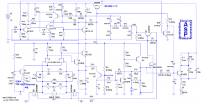
Q14 is indeed purposefully connected in the wrong direction: it is used as a zener diode.And is Q14 in the wrong direction or do i miss something ?
You might ask: why not use a regular zener diode?
Because the breakdown of a very thin, homogeneous planar diode like the BE junction of a transistor is extremely sharp, and has practically no leakage current below the knee, which is essential for the micropower properties of this converter.
Note that this mode of operation will ruin the transistor for all other purposes, but this is completely unimportant here, since it will be its only mode of operation, and at such low current levels, its life will be completely unaffected.
Equipments designed in the 60's and 70's are witness to that: at the time, the BE breakdown voltage was more or less fixed by technological constraints at ~6 to 6.5V, which was ideal for thermal compensation by a forward biased diode, which means it was abundantly used, even in IC's like the much loved 723.
Nowadays, the breakdown limit for GP discretes has moved higher, and is rarely lower than ~7V for PNP's and 8V for NPN's (and it can go much higher, sometimes 15V or more), but the remarkable properties are still present
If you put the protection inside the speaker housing can't you still use the input?
DC-fault, you get also DC for the circuit and to much AC you can rectify that no ?
About using the b-e junction as a zener, i know it, but the junction has to be reverse biased, with PNP transistor base at positive.You have the emitter positive !
Mona
DC-fault, you get also DC for the circuit and to much AC you can rectify that no ?
About using the b-e junction as a zener, i know it, but the junction has to be reverse biased, with PNP transistor base at positive.You have the emitter positive !
Mona
I did give it a thought: use a small fraction of the input to trickle-charge a buffer NiMh cell, but in the end, I rejected it, as it required rectification, in other words drawing a non-linear current from the signal. OK, it's very low Z, but I preferred to avoid it.If you put the protection inside the speaker housing can't you still use the input?
DC-fault, you get also DC for the circuit and to much AC you can rectify that no ?
It could still be easily added to the existing circuit.
Well spotted!About using the b-e junction as a zener, i know it, but the junction has to be reverse biased, with PNP transistor base at positive.You have the emitter positive !
Here is the corrected version: I cannot place it in the first post, as the forum doesn't allow changes in attachments.
If a moderator see this, maybe he can do it?
Attachments
Last edited:
Elvee, any practical pointers as how to make L1, L2,
and what kind of part can be used for BZ1 (I guess it's a quartz oscillator?)
and what kind of part can be used for BZ1 (I guess it's a quartz oscillator?)
L1 and L2 can be off-the-shelf, medium size drum core chokes (resistor-like chokes aren't generally suitable: they have too much resistance).
I wound L2 myself, because it was faster than ordering it, but a normal 390µ drumcore should work perfectly.
BZ1 is just any passive (without oscillator) piezo-buzzer.
You can pick anyone you prefer here for example:
Pin type Piezoelectric Sounders | Piezoelectric Sounders / Buzzers | Sound Components (Buzzer) | Murata Manufacturing Co., Ltd.
Murata is only one of the many manufacturers possible, and they all have similar products
Now that the thread has been unlocked, I can post some .ASC.
There are others, but I think they are partly duplicate which is why I didn't include them.
If you think something is missing, just tell me and I'll try to include them.
Note that the project has been bench-tested, but not yet included in the target: I have experienced many setbacks, like COVID, cancer and other issues, but I try to catch up (slowly)
There are specific files for the buzzer driver, DC-DC converter, but they are included inthe complete circuit
Attachments

- Home
- Amplifiers
- Solid State
- A.S.P. - Version 2.0