Hi everybody and thank you for this good site.
I am looking for informations concerning a SONY TA N7 amplifier.
I have bought this unit in "not working" conditions.
After some control I have seen that some fuses resistors was blown and some others had been replace by normal resistors.
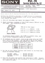
I did not wanted to take the risk to power the amplifier so I decided to test all the VFET transistors by using the SONY bulletin No 52
This bulletin gives for good transistor:
S to D : résistance = 1 to 2 ohm
S to G : same as a diode
D to G : same as a diode
The amplifier is composed of 12 VFET pieces, ten of them are fiting perfectly with the test procedure , for the 2 last pieces the S to G and D to G junctions test confirm it is a diode ( it's ok) but the resistance is respectiveley 2,7 and 3,7 ohms ( all the 10 others are giving 2 ohms)
I suppose these two VFET are faultly but I am not sure, does anybody have any experience about this subject)?
Strangly the two bad VFET were not located in the same leg of the left amplifier.
Thanks for your help and sorry for my "frenchglish" langage
I am looking for informations concerning a SONY TA N7 amplifier.
I have bought this unit in "not working" conditions.
After some control I have seen that some fuses resistors was blown and some others had been replace by normal resistors.
I did not wanted to take the risk to power the amplifier so I decided to test all the VFET transistors by using the SONY bulletin No 52
This bulletin gives for good transistor:
S to D : résistance = 1 to 2 ohm
S to G : same as a diode
D to G : same as a diode
The amplifier is composed of 12 VFET pieces, ten of them are fiting perfectly with the test procedure , for the 2 last pieces the S to G and D to G junctions test confirm it is a diode ( it's ok) but the resistance is respectiveley 2,7 and 3,7 ohms ( all the 10 others are giving 2 ohms)
I suppose these two VFET are faultly but I am not sure, does anybody have any experience about this subject)?
Strangly the two bad VFET were not located in the same leg of the left amplifier.
Thanks for your help and sorry for my "frenchglish" langage
Are you testing these out of circuit ?
A reading of 1 to 2 ohm between S and D (and if that is normal as per Sony) mean that these are depletion mode type FET's and are normally on with no G-S voltage differential.
Knowing whether these are depletion or enhancement mode FET's is the first step to testing and understanding the readings.
Edit... try momentarily shorting G to S before you measure the D-S resistance.
Thanks for your reply,
The V fet technology is not similar with FET transistor, normaly the conduction of transistor is present when the componant is not commanded.
I is why the command electonic is very sensitive ( risk of short circuit)
Normaly most of failed FET transistor are in short-circuit, for VFET I have no experience and I am surprised because the measurement are very close with the nomal values
The service bulletin:
http://www.amplimos.it/images/Sony TA 4650.pdf
Thanks again for your help
These FET's are different to the common types in use today and are normally 'on' when no voltage difference exists between G and S. They are turned off by making the gate either positive or negative (depending whether it is an N or P channel FET) with respect to the source.
Momentarily connecting G to S should remove any charge and allow a true reading to be obtained.
If you have been testing the G-S and G-D junctions then your meter test voltage may well have left the junction charged (like a capacitor) and that could give a false reading as that voltage could be holding the device partly off.
That is why you need to remove any charge between G and S first.
Hi again.
Finaly I have taken the time to do the test now when I came back from my job.
I have shorted the 2 two terminals and the body of the transistor during 10 s
Thn I have got the following measurements:
For the 2SJ18 I have got 2.7 ohms ( 2.1ohms)
For the 2Sk60 I have got 3.6 ohms ( 3.ohms)
The values in red are taking account of my multimeter plug impedance ( 0.6 ohm)
Compare to the other V mos there is aroud 2 ohms ( 1.4 ohms)
Yesterday when I have measured for the first time I was waiting for a stable value ( I think the multimetre was discharging the V MOS parasit capacitor during this time)
For the the others 10 transistors the stabilisation is much more faster (no need to wait)
Thanks for your reply
Last edited:
So you think these two FET's are suspect ?
I've just measured a set of genuine Sony FET's and the results I get are
2SK60= 1.8 ohm
2SJ18 = 1.4 ohm
Are your 2 suspect FET's of the same rank as all the others ?
I've just measured a set of genuine Sony FET's and the results I get are
2SK60= 1.8 ohm
2SJ18 = 1.4 ohm
Are your 2 suspect FET's of the same rank as all the others ?
Unfortunately this sort of condition is difficult to verify completely without a curve tracer.
You can in principle measure if the VFET works using an ohm-meter and a 9V battery with 1k resistor in series.
The ohm meter is connected to D-S (+ on D for K60, - on D for J18).
The battery with 1k in series (there MUST be a resistor in series to guard against an incorrect connection) goes between G and S (+ on S for K60, - on S for J18).
Here is how you measure:
1) Just use your instrument to verify a diode between D-G and S-G. If the VFET does not pass this test, it is dead.
2) Connect S to G (you can use a short circuit, but even better is if you use the 1k resistor). Then measure resistance between D and S (instrument + on D for K60, - on D for J 60). The VFETs should measure 1-2 ohms (depends on the current the instrument passes through the device under test). If it's radically different, the VFET is dead.
3) Connect 9V battery in series with 1k resistor between G and S (battery + on S for K60, - on S for J18). Then measure resistance between D and S as above. The resistance should be MUCH higher than in step 2 - depending on your instrument it can varu a lot but it will at least be tens of k ohms, usually it will show open circuit. If it shows a low resistance the VFET is dead.
HOWEVER. When Vgs=0V and resistance measured is in the low ohm values but not below 2 ohms, there may be a problem with leakage or breakdown damage which results in dramatic reduction of gate sensitivity, and low Vdg and Vds breakdown voltage. This is not easy to measure but a curve tracer will show it immediately.
Specifically regarding TA-N7: PREVENTIVELY REPLACE THE BIPOLAR OUTPUT TRANSISTORS which are used in the BJT-VFET cascode output stage. I've written about this before, to make a long story short, these tend to break down and in various ways take the VFET with them. If they go short or leaky, they can easily destroy a VFET by simply making it permanently on. If they go open, a more insidious mechanism results, that degrades the VFET very similar to your symptoms by provoking Vgs larger than the specified maximum. In time, the VFET gate to channel interface breaks down and the VFET will start behaving strangely, leaking and resulting in full breakdown of it's mated BJT, in turn destroying both.
The preferred substitutions are D44H11 and D45H11.
Thank to Mooly and ilimzn for your help,
Actualy I am not at home so I can just confirm the 2 suspicious fet are from the same rank.
For the tests described by ilimzn I will do them when I will be at home.
Thank again ,
Actualy I am not at home so I can just confirm the 2 suspicious fet are from the same rank.
For the tests described by ilimzn I will do them when I will be at home.
Thank again ,
I wondered about the rank, not so much because the readings would differ but rather it could be a clue that they had been replaced incorrectly in the past.
Interesting......
Interesting......
Good evening
I have done all the tests and they are ok , the results for the test number 3 :
For the K60 with 1kohm + 9V battery : Rds= 13.43 Mohms
For the J18 with 1kohm + 9V battery Rds= 1.21 Mohms
For this point it seem to be ok, I have some doubt about the "eakage or breakdown damage " mentioned by ilimzn.
The two suspicious componants have only a small difference with the others:
- The resistance whithout command is al little higher than 2 ohms
- The junction DS seem to be more capacitive, the multimeter need a few second to display the stabilisated resistance value.
I have one question: if I replace the 9v battery with a variable power supply and mesure the resistance = f(GS) can have a beter idea of the condition of the componants?
I have got from a friend 4 new transitors from a TA4650 they are ok but not from the same rank(mine are JL 54 and the 4 others are JL 55), may be I could do an exchange with somebody.?
The next step will be to check the ouputs bipolars transistors .
Thanks again for your help
Last edited:
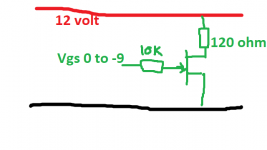
I would probably look to try testing these under more realistic conditions. If you have a variable supply and another voltage source (power supply or decent battery) then I would rig them up so they pass say 100ma as a maximum when on. Place a meter in series with the 120 ohm and check the current at differing Vgs.
I've never done this on a VFET but it is the sort of thing I would look at doing to get a meaningful result.
I've never done this on a VFET but it is the sort of thing I would look at doing to get a meaningful result.
Attachments
Good evening
I am coming back with my vfet problem.
After some research I finaly founded 4 other functionnal VFET but with a different pitch:
The original are 2SJ18 JH-54 and 2SK60 JL-54
The new I have got ( from a TA 4660) are 2SJ18 JG-55 and 2SK60 JL-55
My questions:
-The pitch is the number 55 or 54 and the 3 pairs of one way must have the same pitch. in a TA N7
-If I understand well the TA N7 service manual I can use 6 pieces witch 53or54or55 pitch number for each way.
-What is the signification of the two letters JH/JL and JG/JL
I have the oportinity to make an exchange with a friend , but I want to be sure to understand all the detail of the reading of the VFET componants
Thanks by advance for your help
1) It is not the pitch number, it is the RANK number, and this number is only the LAST digit of the LL-NN code, where L is a letter and N is a number. This has been said MANY times, search will help.
2) TA-N7:
a) the optimum is having the same rank number on all VFETs, the highest you can find.
b) If you cannot assemble a full set with the same rank number, the way to go is assemble 3x J18 with the same rank number and 3x K60 with the same rank number, and the rank numbers of J18 and K60 must not be different by more than 1. This is a close to optimal solution.
c) The least optimal solution that still satisfies the rules given by Sony, is to assemble one set of 3 J18 with rank numbers not different by more than 1, and a set of 3 K60 with rank numbers not different by more than 1. If at all possible the difference between J18 and K60 ranks must not be more than 1.
Example:
a) J18 and K60 all the same rank, say 5
b) All J18 rank 4, all K60 rank 5
c) J18 rank 4,5,4 and K60 rank 5,5,4
3) Signifficance of the first 2 letters and number - this is an encoding of the lot number / date of production. Lower letters by alphabet means older part.
Thank you
Thank you ilimzn for your complete and clear answer.
Sorry for my late reply, I am just coming back from vacations
I have done a lot of research on the net but I did not find all the answers to my questions and some time in function of the discussion I founded differents answer.
Secondly my english is not so good so may be I do not understand some internet post.
I have now all the information to begin my amplifier reparation, Firstly I can make the least optimal version until I will find transistors from the good batch.
Thank you again, I am sure your answer will help a lot of persons.
2sk60
Hi!
I bought a Sony ta-4650.
The first thing i did was take out the Vfet for a check.
With first simple test with a my ohm meter i found that the
2sk60 was out of range it reads about 3,5 ohm.
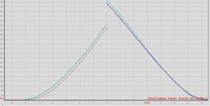
Tried with the curve tracer and found out it's missing lot of amp
and the curve is different..
They are broken, but the 2sj18 seems to be okej.
I had really luck i found 2sk60 HA-56 , exact the sam grade.🙂
Now the work begin with new diods, recap etc.
You can see the picture.
This is 2sj18/2sk60
Hi!
I bought a Sony ta-4650.
The first thing i did was take out the Vfet for a check.
With first simple test with a my ohm meter i found that the
2sk60 was out of range it reads about 3,5 ohm.
Tried with the curve tracer and found out it's missing lot of amp
and the curve is different..
They are broken, but the 2sj18 seems to be okej.
I had really luck i found 2sk60 HA-56 , exact the sam grade.🙂
Now the work begin with new diods, recap etc.
You can see the picture.
This is 2sj18/2sk60
Attachments
Last edited:
Hi everyone.
Question from a beginner. I bought a ta-5650 from ebay and have started to test the vfets. I have remove all of the 2sj18s and have tested them.
They are all hd-55 grade and when I tested the source to drain I got:
.567ohms
.577ohms
.661ohms
.671ohms
Will they all need to be replaced. Is it possible I did something wrong? is it worth continuing to to inspect the 2sk60s?

All of the vfets passed the the diode test, my multimeter just beeps to symbolize continuity.🙂
I think I see what your getting at soundhappy. If I move the leads around when testing resistance I can get a value in between 1-2ohs for all the transistors. I'm afraid I committed a neweb mistake of using the wrong type of leads 😕.
Another question one of the 2sk60s is a different grade than all the other vfets. 7 vfets are grade ha-55 and one 2sk60 is p55. I will test the 2sk60s tomorrow.
- Status
- Not open for further replies.
- Home
- Amplifiers
- Solid State
- VFET testing method and result