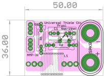
here is an idea for a speaker terminal mounted universal Thiele PCB, that can be used for any amp that either do not have the zobel and /or inductor//resistor on the PCB.
Although thiele ckt can be made point-to-point , a PCB only makes it convenient and compatible with 19mm dual binding posts that are so convenient for using as a speaker terminal in diy amps.
faston/ 5mm pitch terminal block can also be used for amp-in / GND connections.
resistors right from 1/2w to 2w and 3w can be used. zobel cap from 5mm to 15mm pitch, inductor of various lengths with a max dia of about 13mm could be used.
can be diy etched / manufactured.
open for suggestions.
reg
Prasi
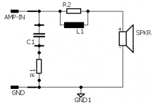
edit, schematic added
Although thiele ckt can be made point-to-point , a PCB only makes it convenient and compatible with 19mm dual binding posts that are so convenient for using as a speaker terminal in diy amps.
faston/ 5mm pitch terminal block can also be used for amp-in / GND connections.
resistors right from 1/2w to 2w and 3w can be used. zobel cap from 5mm to 15mm pitch, inductor of various lengths with a max dia of about 13mm could be used.
can be diy etched / manufactured.
open for suggestions.
reg
Prasi
edit, schematic added
Attachments

Last edited:
ebay link for dual binding post New Speaker Amplifier Terminal Dual Binding Post Banana Plug Jack USA SELLER!!! | eBay
and drawing
http://www.farnell.com/cad/1933991.pdf
and drawing
http://www.farnell.com/cad/1933991.pdf
This location adds cable inductance between the amplifier and the Thiele Network.
The amplifier output Zobel usually requires low inductance to enable the Network to present a low impedance to very high frequencies.
This may result in your circuit not being "Universal" !
The amplifier output Zobel usually requires low inductance to enable the Network to present a low impedance to very high frequencies.
This may result in your circuit not being "Universal" !
Last edited:
as i mentioned in first post, its for those amps that dont have any or either of the components of thiele on amp pcb itself. better to have it here than not having at all, dont you think?
in most cases it should be possible to keep short , thick wires to spk terminal with proper thoughtful layout in cabinet.
in most cases it should be possible to keep short , thick wires to spk terminal with proper thoughtful layout in cabinet.
Last edited:
if an amplifier requires a low inductance Zobel then it must be wired into the output so that low impedance is achieved.
In that situation your circuit could still be used, but then the extra Zobel would be better across the speakers terminals to create the Pi version as mentioned by myself and recently suggested by R.Cordell.
Note, that in your PCB only one trace needs to be changed. The one that runs diagonally under the 15mm label.
This could be done as a option on the PCB, where the Builder adds a solder short across either of the two gaps.
Last edited:
Nice one Prasi. Thanks for sharing - it goes on amp box at banana jack out then? It's interesting how most Pass Class A amps don't have this and most amps in SS have them. Why is that?
it's lots of negative feedback that gives rise to the possibility of phase margins dropping too low.
If a Pass amplifier does not have a lot of gain, it can't have lots of NFB, so doesn't run low on phase margin. i.e. it behaves in the presence of slightly reactive loading.
If you have one stage and the gain falls at 6dB/octave as frequency rises, then the most phase delay at the output one can get is 90degrees.
If one has two stages and each falls at 6dB/octave then when the frequency goes high enough you can end up with 180degrees of phase delay. But if that occurs at a frequency where the gain has fallen significantly below 1 then the phase margin remains adequate.
It's when you cascade three stages to obtain very high open loop gain that the phase delay goes ultimately to 270degrees that one can approach 180degrees of phase delay while the gain is still above 1 that we end up with inadequare hase margin.
Last edited:
I am a little bit puzzled that this combination is called a "Thiele network". He published an article in the JAES (back in the 1970's I think) where he proposed a series of stabilizing networks but they were not the one shown here.
I'll try and describe the first of them.
If you refer to the schematic in prasi's #1 post I will describe it as Thiele published it. Delete the Zobel (C1 R1) completely and then shunt the speaker with a small capacitor AFTER the parallel L1R2 combination. Simple. I know this looks wrong at first sight but a moments reflection will show that the cap will never "short" the output as the impedance at high frequencies will never be less R2 in parallel with L1 (which of course rises with increasing frequency). The original article is well worth finding. The point he made was that when connected to a speaker it generally presented the amp with an essentially constant load if the speaker was assumed to be more or less resistive. The network as I described it was popularized here in Australia (his home) with a series of diy amps from the mid '70's onwards.
But this was only the first order version. In the JAES article he goes on to show 2nd and 3rd order networks. These not only stabilized the amp' but he stressed they also acted as RFI filters of any rubbish picked up by the speaker cables. One particularly elegant version had the feedback taken from a bifilar winding from one of the inductors.......(don't ask me to remember the whole of this network as it is getting quite complicated with the 3rd order system).
The values could be optimized for various speaker impedance.
Just from memory the widely used version published here for a diy 25 watt into 8ohms domestic stereo amp' was as follows. R//L 8 ohms and 22mH. The cap across the speaker output terminals was a 0.22uF polyester film. I'll check those values as it was 36 yrs since I built one. But I think they are correct.
I'll try and locate the reference as it represents his typically elegant and creative thinking.
And just to add a bit of local trivia I am posting this from the city (Brisbane) where Neville Thiele was born and as it happens, just by coincidence, today is Australia Day too!
Cheers, Jonathan
Last edited:
I have not seen the original paper/s of Neville Thiele.
I got my information from the articles written By E.Cherry.
He stated that N.Thiele published two versions where the L||R is similar in both versions.
The difference between them was in the location of the Zobel.
Version 1 showed the L+R at the amplifier followed by the L||R in series to the amplifiers speaker terminals.
Version 2 showed the L||R in series and the Zobel capacitor across the amplifiers output terminals. I called version 2 a "Zobel" because the R of the L||R is in series with the Capacitor and still forms an R+C when the inductor is passing virtually no current at the high frequencies where the stabilising network operates.
E.Cherry went on to explain that the two Thiele versions were at opposite extremes of a continuum and showed how he would use intermediate values between the extremes.
I posted a spreadsheet showing the E.Cherry method of analysis and in it gave a reference to the Cherry article.
http://www.diyaudio.com/forums/solid-state/94029-when-output-inductor-needed.html#post1105724
And posted it again a few more times.
Note in the bottom line just above the diagram I have:
R1b any value, R1b=0 gives Thiele's original, i.e. R2 = Rload
then you see that C is alone across the speaker terminals just as Jon has described in post8
Leach used Version 2 in the Lo Tim amplifier
Last edited:
Thanks Andrew. I also recall this area being covered in one of two Edward Cherry articles the old E&WW. I am guessing they are the ones you are refering to. They were entitled "Ironing out distortion" (Parts 1 and 2) or something like that....
Again in the Bright archives somewhere and will emerge in the fullness of time.....I hope.
Cheers Jonathan
Again in the Bright archives somewhere and will emerge in the fullness of time.....I hope.
Cheers Jonathan
the ref was:Thanks Andrew. I also recall this area being covered in one of two Edward Cherry articles the old E&WW. I am guessing they are the ones you are refering to. They were entitled "Ironing out distortion" (Parts 1 and 2) or something like that....
Again in the Bright archives somewhere and will emerge in the fullness of time.....I hope.
Cheers Jonathan
from Dr Cherry: Electronics world jan'95 & jul'97
Do you want me to put zobel (C1,R1) at the locations of R1b and Cb as per the excel document you referenced??if an amplifier requires a low inductance Zobel then it must be wired into the output so that low impedance is achieved.
In that situation your circuit could still be used, but then the extra Zobel would be better across the speakers terminals to create the Pi version as mentioned by myself and recently suggested by R.Cordell.
Note, that in your PCB only one trace needs to be changed. The one that runs diagonally under the 15mm label.
This could be done as a option on the PCB, where the Builder adds a solder short across either of the two gaps.
BTW Nice discussion on Thiele ckt Andrew and Jonathan. Thanks for the valuable info.
to Xrk,
yes , the pcb mounts on banana spk terminal
reg
Prasi
You don't have to move the L+R.
It would be very easy to offer the option to locate the L+R before OR after the L||R.
The option is in the trace under the 15mm label and can be selected by the Builder at time of assembly.
i.e. the right hand end of C1 can connect to the left hand end of R2 as you have shown
or
the right hand end of C1 can connect to the right hand end of R2.
The advantage of adopting the Thiele version 2 network is that when a Version 1 Zobel is on the amp PCB, this Prasi addition at the speaker terminals gives a Pi version of the Thiele Network. This is part of what Jon was referring to.
It is what I have been using for a few years.
It gives good HF performance to the benefit of the amplifier and it gives extra attenuation of interference coming in from the long aerials we call speaker cables.
This speaker cable interference is injected into the -IN node of the amplifier
Some amplifiers actually add a capacitor across the upper feedback resistor to allow direct injection of interference into the -IN node.
Last edited:
Andrew (and others) this is the reference I promised you some time ago.
The article by Neville Thiele is from the "Journal of Audio Engineering" (JAES) 1976 Volume 24 Number 1 pages 20-23. "Load Stabilizing Network for Audio Amplifiers".
Btw guys if you are not familiar with this source it can be a mine of information. When I first discovered it over 45 yrs ago a number of tertiary institutions and public libraries carried it and they provided easy "walk in" access and copying facilities. Not quite so easy now. For us diyers I found the material from the 60's, 70's and early 80's was very useful. For me the subsequent move to a digital emphasis was less attractive.
If you were not a member of the AES you used to be able to order individual articles (hard copies) from The AES for about $5 a copy (now $35 I think). Now there is a substantially higher charge that gives you access to a lot of the material including their conference papers that were never published in the Journal. You will need to check but it looks like you can acquire an Associate Membership for US$125 a year and get access to over 16,000 items going back to 1953.
There is a wealth of stuff there.
Cheers Jonathan
Last edited:
Ok, thanks for explaining.
Here is the revised version. Either of the jumpers J1 or J2 could be used to make the appropriate zobel either across amp-in or across speaker terminals..
reg
Prasi
here are the eagle files for anyone interested.
reg
Prasi
Attachments

- Status
- Not open for further replies.
- Home
- Amplifiers
- Solid State
- universal thiele circuit