Power Amplifier with Small Signal OP-Amp in the Front-End - Overview and Books wanted
There are a lot of topologies for such amplifiers, but I filed they into two main groups:
1) Signal pad by voltage supply rails of small signal operational amplifier
http://sound.westhost.com/ad_fig16.gif
http://nacl.de/audiomap/sac_50.gif
http://www.diyaudio.com/forums/solid-state/41034-abacus-rieder-60-120-amplifier.html (post #5)
Bild: dacmos300jh8qu4m.jpg - abload.de
http://www.analog.com/media/en/tech...tes/58052492001115525484056221917334AN211.pdf
http://www.diyaudio.com/forums/soli...pamp-signal-pad-power-supply-rail-naming.html
2) Signal pad by output of small signal operational amplifier (both with aditional VAS and without, i. e. only CFP booster/power follower)
300W Power Amplifier Elektor | Ave Circuits
50W OCL main amplifier using LF351-2N3055-MJ2955 PCB
http://home.mira.net/~gnb/audio/images/LM143-AudioPowerAmp2a50.jpg
http://www.eleccircuit.com/wp-conte...r-amplifier-ocl-35w-by-ne5402n3055-mj2955.jpg
http://www.eleccircuit.com/wp-content/uploads/2010/04/power-amp-ocl-70w-with-ic-741-2n3055mj2955.jpg
http://electronics-diy.com/schematics/911/01.jpg
http://www.eleccircuit.com/wp-conte...cuit-power-amp-ocl-50w-with-lm3900-2n3055.jpg
http://daub-endstufen.de/daub_d500ab/end.htm
http://www.mikrocontroller.net/attachment/133490/opes1.jpg
How many important versions are to distingued and what are the pros and cons of the various approaches ?
For the stability of the quiescent current (idle current) through the output power stage e. g. I note a lot of approaches.
Also of interest is the question, which of the currently available top quality op-amps are suited for the various versions.
Are there amplifier books particularly with focus of this topic?
Thank you for advices, even to already exist threads to this topic here on diyaudio.
Last edited:
Two to add to the second category:
https://www.by-rutgers.nl/SSA-30W.html
https://www.by-rutgers.nl/PDFiles/SSA120.pdf
I recently researched these two approaches to come to the amplifier I am playing with now.
I came to the conclusion to build an amplifier of the second type, with ADA4700-1 and CFP buffer mutated towards CFA (similar to SSA-35 approach, but different feedback connection to maintain stable bias without thermistor).
My own observations were: Alexander topology (an amplifier of the first kind) is both more flexible and less flexible at the same time. Effects of thermal and SOA management functions common in modern opamps but not shown in simplified circuits are difficult to predict without actual tests. Some key parameters such as PSRR can be degraded and and stabilisation is potentially non-trivial. But at the same time you can use a higher variety of opamps as well as manipulate feedback factor much more intricately.
Putting together something of the second topology is far more trivial, but you do not have a whole lot of options for the front end when it comes to rails above 18V. OPA445, OPA552, LTC6090 and of course the ADA4700-1 that I used, are some that are in current production. You could also consider the phased out LME49810/11/30 to be types of front end too. The common theme for downsides being the restricted slew rates.
For me the ADA4700-1 appeared to me to have the best balance of performance over the competitors I considered. It doesn't leave much room to move though being unity gain compensated, but my purposes fit inside the envelope.
Another one of the first type. By chance, I was looking at it earlier today.
http://www.electroschematics.com/wp-content/uploads/2008/04/mosfet-power-amp-irf9530-irf530.gif
This topology doesn' t look right at first glance. Then you take a closer look and think: "yeah, that could work."
http://www.electroschematics.com/wp-content/uploads/2008/04/mosfet-power-amp-irf9530-irf530.gif
This topology doesn' t look right at first glance. Then you take a closer look and think: "yeah, that could work."
Another one of the first type. By chance, I was looking at it earlier today.
http://www.electroschematics.com/wp-content/uploads/2008/04/mosfet-power-amp-irf9530-irf530.gif
This topology doesn' t look right at first glance. Then you take a closer look and think: "yeah, that could work."
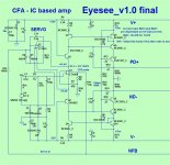
(below) is one that IS working ...
Eyesee got thrashed by member Still4given.
-perfect clip , full 200W+ through the EF3.
He said it was comparable to the standard leach/blameless input stages
with the right op-amp.
OS
Attachments
I have always wondered about the SAC 50 circuit if a small cap let's say 2.2 uF connected from the emitter of T1 to ground and the same at T2 would improve the power supply of the op-amp or would worsen/malfunction the circuit.
Could someone help me?

Could someone help me?
Last edited:
You don’t need big caps there - you don’t actually want them. .01 uf’s right at the op amp pins are often helpful - especially if you have something else sharing that power supply (such as a DC protect, fan temp controller, limiters, or other stages). Bigger caps just put the pass transistors under stress on start up. C3 and C4 can be made large (100 or more uf) and that gets rid of the zener noise as well as ensuring a controlled start up.
The supply rails of the operational amplifier are signal outputs at the same time on this approach. This means, that capacitors at this nodes create a low pass character.You don’t need big caps there - you don’t actually want them. .01 uf’s right at the op amp pins are often helpful - especially if you have something else sharing that power supply (such as a DC protect, fan temp controller, limiters, or other stages). Bigger caps just put the pass transistors under stress on start up. C3 and C4 can be made large (100 or more uf) and that gets rid of the zener noise as well as ensuring a controlled start up.
Because this happened inside the NFB-Loop, it isn't possible to predict what happens without simulation by CAD software like ORCAD.
Ask Mr. Bob Cordell for more advices concerning this.
From this brand I am looking for schematic and inside images of the model "The Amplifier" from SAC's "Mediatore" series - go toI have always wondered about the SAC 50 circuit if a small cap let's say 2.2 uF connected from the emitter of T1 to ground and the same at T2 would improve the power supply of the op-amp or would worsen/malfunction the circuit.
Could someone help me?
https://www.diyaudio.com/forums/sol...fier-schematic-images-inside.html#post6325966
test in the German magazine STEREOPLAY 3/89
I am looking for commercial amplifier models used one of this mentioned topology and tested here:There are a lot of topologies for such amplifiers, but I filed they into two main groups:
1) Signal pad by voltage supply rails of small signal operational amplifier
http://sound.westhost.com/ad_fig16.gif
http://nacl.de/audiomap/sac_50.gif
Abacus rieder 60-120 amplifier - diyAudio (post #5)
Bild: dacmos300jh8qu4m.jpg - abload.de
http://www.analog.com/media/en/tech...tes/58052492001115525484056221917334AN211.pdf
http://www.diyaudio.com/forums/soli...pamp-signal-pad-power-supply-rail-naming.html
2) Signal pad by output of small signal operational amplifier (both with aditional VAS and without, i. e. only CFP booster/power follower)
300W Power Amplifier Elektor | Ave Circuits
50W OCL main amplifier using LF351-2N3055-MJ2955 PCB
http://home.mira.net/~gnb/audio/images/LM143-AudioPowerAmp2a50.jpg
http://www.eleccircuit.com/wp-conte...r-amplifier-ocl-35w-by-ne5402n3055-mj2955.jpg
http://www.eleccircuit.com/wp-content/uploads/2010/04/power-amp-ocl-70w-with-ic-741-2n3055mj2955.jpg
http://electronics-diy.com/schematics/911/01.jpg
http://www.eleccircuit.com/wp-conte...cuit-power-amp-ocl-50w-with-lm3900-2n3055.jpg
http://daub-endstufen.de/daub_d500ab/end.htm
http://www.mikrocontroller.net/attachment/133490/opes1.jpg
How many important versions are to distingued and what are the pros and cons of the various approaches ?
For the stability of the quiescent current (idle current) through the output power stage e. g. I note a lot of approaches.
Also of interest is the question, which of the currently available top quality op-amps are suited for the various versions.
Are there amplifier books particularly with focus of this topic?
Thank you for advices, even to already exist threads to this topic here on diyaudio.
https://www.stereophile.com
thank you for an advice
Last edited:
@tiefbassuebertr:
Looks like you are preparing for a deep investigation of some kind.
Please tell us about your scope and rational, what are you going to accomplish?
I assume, that you are aware about
- Douglas Self, Audio Power Amp Design Handbook, 6th edition
- CordellAudio.com - Designing Audio Power Amplifiers
I am currently busy on a spice-simulation-based benchmarking project looking at various amp-topologies; very time-consuming & very intersting...interested?
T2US, sepp2gl
how would sound the "best" op amp based preamp followed by a pass F4?
if the output impedance of the op amp preamp is low it could drive the mosfets of the F4 without the 107/74 Jfet buffer....
if the output impedance of the op amp preamp is low it could drive the mosfets of the F4 without the 107/74 Jfet buffer....
@tiefbassuebertr:
This looks like you are going to make a deep investigation.
Are you aware of
- Self - Audio Power-Amplifier Design Handbook, 6th Edition
- CordellAudio.com - Designing Audio Power Amplifiers
I am currently doing a spice-simulaton-based benchmark-project looking at various amp-topologies. Much work, but very interesting...interested?
T2US, sepp2gl
first happy new year to all.
the QUAD 405 is a special case in that it consists of a combination of a single-ended class-A stage as correction resp. error amp and a PP output stage in pure class-B (current dumping) - go to
Peter Walker and his current dumping principle
Quad 405 clone
QUASAR a QUAD405 reborn design
Yamaha's Hyperbolic Conversion Amplification (HCA) Circuit
Yes, mainly to find and compare the stereophile measurements like those examples under
https://www.stereophile.com/content/classé-delta-mono-monoblock-power-amplifier-measurements
or
https://www.stereophile.com/content/ps-audio-stellar-m1200-monoblock-power-amplifier-measurements
for me the most interesting diagram is the distortion and noise waveform with fundamental notched out (go in both URL's to Fig. 8).
If you compare a wide range of amplifiers you will note, that only amplifiers have good sound in the midrange and particularly in the high frequency area, where the residual distortion has a nearly sine wave character, regardless of the amount of distortion. This is the reason, why class-A solid state amps (especially single ended versions like ZEN/Aleph) and tube amps sounds good and class B and class D amps sounds more harsch and crispy.
The aim of the efforts is to find out class B solid state variants with the same character of distortion than class-A and tube amps.
P.S.: check out this thread concerning audio amplifier books (if URL is death go to https://web.archive.org)
The best audio amplifier books - Overview (Google books)
the QUAD 405 is a special case in that it consists of a combination of a single-ended class-A stage as correction resp. error amp and a PP output stage in pure class-B (current dumping) - go to
Peter Walker and his current dumping principle
Quad 405 clone
QUASAR a QUAD405 reborn design
Yamaha's Hyperbolic Conversion Amplification (HCA) Circuit
@tiefbassuebertr:
This looks like you are going to make a deep investigation.
Are you aware of
- Self - Audio Power-Amplifier Design Handbook, 6th Edition
- CordellAudio.com - Designing Audio Power Amplifiers
I am currently doing a spice-simulaton-based benchmark-project looking at various amp-topologies. Much work, but very interesting...interested?
T2US, sepp2gl
Yes, mainly to find and compare the stereophile measurements like those examples under
https://www.stereophile.com/content/classé-delta-mono-monoblock-power-amplifier-measurements
or
https://www.stereophile.com/content/ps-audio-stellar-m1200-monoblock-power-amplifier-measurements
for me the most interesting diagram is the distortion and noise waveform with fundamental notched out (go in both URL's to Fig. 8).
If you compare a wide range of amplifiers you will note, that only amplifiers have good sound in the midrange and particularly in the high frequency area, where the residual distortion has a nearly sine wave character, regardless of the amount of distortion. This is the reason, why class-A solid state amps (especially single ended versions like ZEN/Aleph) and tube amps sounds good and class B and class D amps sounds more harsch and crispy.
The aim of the efforts is to find out class B solid state variants with the same character of distortion than class-A and tube amps.
P.S.: check out this thread concerning audio amplifier books (if URL is death go to https://web.archive.org)
The best audio amplifier books - Overview (Google books)
Last edited:
I absolutely agree, in this topology you're trying to 'sense' all of the opamp supply current (as a measure of the signal current), so adding any capacitance will shunt some of this away from the transistor emitters and reduce the curent sensing effect. In addition, the impedance looking into the emitters will be quite low, so the impedance of any capacitor will only have an effect towards the HF end.The supply rails of the operational amplifier are signal outputs at the same time on this approach. This means, that capacitors at this nodes create a low pass character.
Because this happened inside the NFB-Loop, it isn't possible to predict what happens without simulation by CAD software like ORCAD.
Ask Mr. Bob Cordell for more advices concerning this.
Tube amplifiers use output transformers to connect loudspeakers. They are a radio frequency filter.
The analogue on the forum is the Zeus amplifier Susan Parker.
Class D amplifiers with high efficiency practically use digital conversion. In this case, losses in the lower digits are inevitable (microdynamics).
Class B has a loss of conductance control when the signal crosses zero (switching distortion).
The AB class masks the switching distortion, and the distortion of the transfer characteristic is partially compensated by the deep NFB.
The 405 combines a low-power output A with a high-power stage B.
Hi, your first category utilises the 'supply current sensing' technique, which was used to create the first current-feedback topologies using conventional voltage opamps. The whole supply current fairly closely matches the output current, which is ideally what is required in this topology, with the 'error' from biassing relying on the overall loop gain to attenuate. Providing seperate supply pins for the opamp output devices would allow only the output current to be sensed for greater accuracy, as would an additional discrete current buffer stage after the opamp.
One key difference between the first and second categories, is that in the first the overall negative feedback is current, which in theory allows larger slewing currents of the first stage and some independance of the closed loop bandwidth from the closed-loop gain and Gain Bandwidth Product, whereas the second uses conventional voltage feedback. As to which is preferred - that will depend a lot on the detailed implementation!
One key difference between the first and second categories, is that in the first the overall negative feedback is current, which in theory allows larger slewing currents of the first stage and some independance of the closed loop bandwidth from the closed-loop gain and Gain Bandwidth Product, whereas the second uses conventional voltage feedback. As to which is preferred - that will depend a lot on the detailed implementation!
I just finished a project using OPA552 (±30 volt rails, Iout=200mA when output pin is 3.5V from rail) in a DIP-8, thru hole package. Connecting a unity gain current booster output stage (double emitter follower et al) would give 35W RMS into an 8 ohm load.
ADA4700 would go much higher, as mentioned above. But it's not available in thru hole packaging -- for excellent (thermal) reasons.
ADA4700 would go much higher, as mentioned above. But it's not available in thru hole packaging -- for excellent (thermal) reasons.
- Home
- Amplifiers
- Solid State
- Power Amplifier with Small Signal OP-Amp in the Front-End - Overview wanted