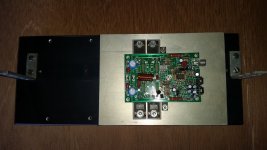
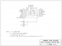
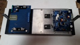
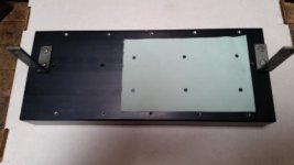
The time and cost to build a rack mount amplifier can be many hours and cost hundreds. I would rather spend my time designing and testing amplifiers. I wanted to design a universal amplifier chassis to accommodate several different amplifier sizes. Each amplifier has an adapter plate that is drilled to match the power devices and mounts on the heat sink. Thermal compound between the adapter plate and the heat sink conducts the heat to the heat sink. The adapter plate seen in the pictures is 10” x 4.75”. The interface board utilizes the existing chassis connector and provides a terminal block for easy connections to various amplifier boards.
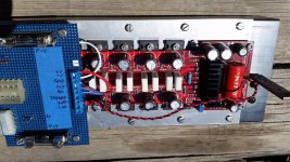
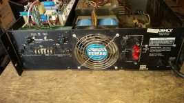
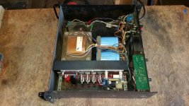
The nonworking Ashly FTX-2000 Amplifier was $45 and it has a level control board, fan, heat sinks, power transformer (1,800 VA), good caps (16,000 uF, 100V), and VU display. The power supply was +/- 84V, I rewired the input for 240VAC to reduce the power supply was +/- 42V. The Ashly FTX-2000 is a 500 W RMS Amplifier with fused outputs and balanced and unbalanced input.
The amplifier mounted on the heat sink is a LME49810 300W Amplifier Board, assembled $50. This makes a 600W rack amplifier for less than $200.
The smaller amplifier board is my design.
Any thoughts for improvements?
Attachments
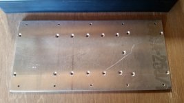
Your countersunk holes look a bit deep.
They are reducing the contact area under the device.
If these were for a clamp bar, where the holes are not under the devices, then it would make no difference to heat flow.
They are reducing the contact area under the device.
If these were for a clamp bar, where the holes are not under the devices, then it would make no difference to heat flow.
a double row of inline pins to take a daughter board with a matching double row socket is very useful for "plug in" experiments.
0.1" single and double pins/sockets/headers are very available.
0.1" single and double pins/sockets/headers are very available.
Your countersunk holes look a bit deep.
They are reducing the contact area under the device.
If these were for a clamp bar, where the holes are not under the devices, then it would make no difference to heat flow.
The counter sink holes are not deeper than needed; the heads are flush with the plate and are filled with DOW CORNING® 340.
The area of the counter sink holes is less than 1.5% of the total area of the place. The heat sink is 12” x 5” x 1.5” with 12 fins.
At 500 LFM the heat sink thermal resistance is less than 0.30° C/W.
References:
https://en.wikipedia.org/wiki/Heat_sink
- heatsink design tools
Air Flow Conversion Calculator - ft/meter, m/s, miles/hr, ft3/min, m3/hr, L/s
Flow Velocity Calculator - heat sinks
Not quite understanding Why? One wouldn't simply Mount devices directly onto the heatsink.
An ali interface plate with a whole lottta Goop on it.. is just an another path impediment to heat loss.
Suppose as a Make do for recycling some old Thrift store box its Ok. But beyond that?
An ali interface plate with a whole lottta Goop on it.. is just an another path impediment to heat loss.
Suppose as a Make do for recycling some old Thrift store box its Ok. But beyond that?
The adapter plate solves the problem of over lapping holes and it allows
low power bench testing before it’s mounted on the large heat sink.
Say you wanted to test 10 or more different amplifier boards and the heat
sink holes overlap, where half of one hole lines up with an existing hole.
The full size Sil-Pad Thermal sheet eliminates the need for thermal compound.
The large heat sink with forced air is has plenty of cooing capacity, the small added Thermal resistance has been taken to account and does not create a problem.
The same configuration is used in many motor controllers. The Sil-Pad seen in the picture is form a Curtis 1204 400 Amp motor controller.
Attachments
Last edited:
looks like some good bones you bought there.
looking forward to that day you report full rail voltage achieved.
looking forward to that day you report full rail voltage achieved.
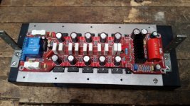
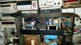
I installed a NAP-140 Amp, using +/- 42 V supplies. I ran the amp near clipping with a 4 ohm load. The interface plate was a little warm after about 5 min., but the 12” x 5” heat sink felt the same temperature as the surrounding metal. Without the amp cover, the fan moves almost no air. The fan turns very slow to keep the noise down.
I'm very happy with the adapter plate interchangeability and the cost of just a few dollars each. A heat sink of this size is over $65 each and would be very expensive to buy a pair of heat sinks for many different amplifiers.
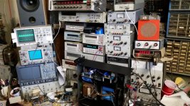
Here are some pics of the amp under test on my bench.
I'm very happy with the adapter plate interchangeability and the cost of just a few dollars each. A heat sink of this size is over $65 each and would be very expensive to buy a pair of heat sinks for many different amplifiers.
Here are some pics of the amp under test on my bench.
Attachments
- Status
- Not open for further replies.
- Home
- Amplifiers
- Solid State
- Low cost universal amplifier chassis