Hey guys! 🙂
I recently invested in an old Musical Fidelity A1; one of the original ones without ventilation holes.
The problem I am experiencing is that the right channel seems to be playing at a lower volume and with less definition than that of the left channel. - I was encouraged by an electromechanic to test the volume potentiometer, but the problem was still present at max volume.
We came to the conclusion that the problem must exist with the electrolytic capacitors or a worn down gold-plating on the relay contacts.
- I, inexperienced as I am, (Might as well be honest😉) am planning to crack this thing open and see if I can figure out how to replace these capacitors.
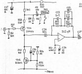
He send me these guidelines for what caps to replace: " [See schematic] - C6 and C7 should be replaced with foil capacitors, C13, C14 and C10 should be replaced with foil capacitors or bipolar electrolytics. "
Can anyone refer me to which capacitors (with what specific specifications) I should purchase? - Preferably from eBay or europe-audio.com, as I live in Denmark.
Thanks guys!
A1 Schematic (Credits to Mark Hennessy):

I recently invested in an old Musical Fidelity A1; one of the original ones without ventilation holes.
The problem I am experiencing is that the right channel seems to be playing at a lower volume and with less definition than that of the left channel. - I was encouraged by an electromechanic to test the volume potentiometer, but the problem was still present at max volume.
We came to the conclusion that the problem must exist with the electrolytic capacitors or a worn down gold-plating on the relay contacts.
- I, inexperienced as I am, (Might as well be honest😉) am planning to crack this thing open and see if I can figure out how to replace these capacitors.
He send me these guidelines for what caps to replace: " [See schematic] - C6 and C7 should be replaced with foil capacitors, C13, C14 and C10 should be replaced with foil capacitors or bipolar electrolytics. "
Can anyone refer me to which capacitors (with what specific specifications) I should purchase? - Preferably from eBay or europe-audio.com, as I live in Denmark.
Thanks guys!
A1 Schematic (Credits to Mark Hennessy):
Last edited:
Can't open your link.
If the amp is DC coupled, then only the feedback return cap (which is usually an electroylitic) can influence gain together with (possibly, but it would be rare) the input coupling cap.
If one channel is genuinely lower in output then look at the feedback components because these determine the gain of the amp.
Attachments

Can't open your link.
If the amp is DC coupled, then only the feedback return cap (which is usually an electroylitic) can influence gain together with (possibly, but it would be rare) the input coupling cap.
If one channel is genuinely lower in output then look at the feedback components because these determine the gain of the amp.
The link should be fixed now.
I have virtually no experience with electromechanical engineering, so I really wouldn't know where to start with "looking at the feedback components". Anyway you could explain to me how I would go about this?
Found it on his pages. Yep, C7,C10,C13 and C14 are the ones to look at replacing. They are shown as standard polarised types. I would probably replace like for like, at least to begin with but add the proviso that you should actually measure the DC voltage across the caps and fit them polarity wise according to the DC voltages you measure. For example, if C10 has say 50 mv DC across it then fit the cap according to the polarity of the offset with the plus terminal to the point of highest voltage. You must measure across the caps to determine this and not the voltage from ground to each lead.
Lets try this as a link to the main page,
Musical Fidelity A1 › Technical
Lets try this as a link to the main page,
Musical Fidelity A1 › Technical
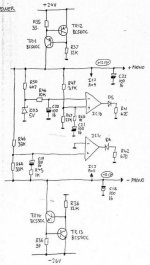
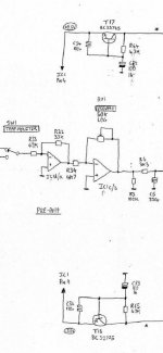
Got such a "handmade" schematic some time somewhere.
It's an interesting amp, especially in terms of "current sensing" NFB in the power section. Lots of electrolytic caps though...
Hope this helps 😉
Ah... Mooly - you're faster )
It's an interesting amp, especially in terms of "current sensing" NFB in the power section. Lots of electrolytic caps though...
Hope this helps 😉
Ah... Mooly - you're faster )
Attachments

Seems like I can't post my original post with the image attached.
No matter. They are the same drawings that vzaichenko has so generously shared. 🙂
Here is the original post again, though. Seems like it got deleted:
I recently invested in an old Musical Fidelity A1; one of the original ones without ventilation holes.
The problem I am experiencing is that the right channel seems to be playing at a lower volume and with less definition than that of the left channel. - I was encouraged by an electromechanic to test the volume potentiometer, but the problem was still present at max volume.
We came to the conclusion that the problem must exist with the electrolytic capacitors or a worn down gold-plating on the relay contacts.
- I, inexperienced as I am, (Might as well be honest😉) am planning to crack this thing open and see if I can figure out how to replace these capacitors.
He send me these guidelines for what caps to replace: " [See Vzaichenko's post #5] - C6 and C7 should be replaced with foil capacitors, C13, C14 and C10 should be replaced with foil capacitors or bipolar electrolytics. "
Can anyone refer me to which capacitors (with what specific specifications) I should purchase? - Preferably from eBay or europe-audio.com, as I live in Denmark.
Thanks guys!
Why not replace those caps with similar parts first to see if it resolves the issue. They cost buttons, are available "anywhere" and would take minutes to replace.
If you really want foil caps and so on then you are going to have to do the legwork and measure the physical dimensions and lead pitch to make sure any replacements will actually fit.
So as to your question... working voltage and capacitance value are the two electrical parameters that need to be checked. Working voltage of replacements can be equal or higher than the originals and I would guess any foil type will be high enough rated voltage wise.
Why not replace those caps with similar parts first to see if it resolves the issue. They cost buttons, are available "anywhere" and would take minutes to replace.
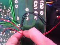
Today I finally received the heatsink compound that I ordered from eBay. So now, following the instructions of Mark Hennessy, I was able to extract the circuit board and take a gander inside.
.jpg")
I am not able to see any sort of leakage or derformation on the caps. (C14, C13, C10, C7, C6) .. So I'm not exactly sure what to do next.. Or whether I should just try and replace them any way.
.jpg")
.jpg")
I did, however, notice that, while R2 looks nice and mint, R1 looks more weathered, has a crack and the lettering is almost faded away. (reads KNA 412)

What do you guys think? - Could this be the source of the imbalance?
I would just replace those caps. They won't be bulged or anything because there is no electrical stress on them, they will just have dried out and developed a high E.S.R. (equivalent series resistance)
The resistor (you mean in the last photo) looks like it is just the coating that has cracked, maybe even as far back as when the amp was made. The leads look to have been bent very close to the body and that can cause the cracking if not done carefully. As long as it reads OK value wise its fine.
The resistor (you mean in the last photo) looks like it is just the coating that has cracked, maybe even as far back as when the amp was made. The leads look to have been bent very close to the body and that can cause the cracking if not done carefully. As long as it reads OK value wise its fine.
I would just replace those caps. They won't be bulged or anything because there is no electrical stress on them, they will just have dried out and developed a high E.S.R. (equivalent series resistance)
The resistor (you mean in the last photo) looks like it is just the coating that has cracked, maybe even as far back as when the amp was made. The leads look to have been bent very close to the body and that can cause the cracking if not done carefully. As long as it reads OK value wise its fine.
Alright! - So I've written down the specifications of each capacitor (10 in total, if I'm being correct?) - C14 is 47uF, C13 47uF, C10 10uF, C7 1uF, C6 1uF.. I'm figuring the voltage rating won't an issue as long as I keep it at the same and/or higher than then ones already on the board. I have noticed that the C10 capacitor has 16v on one side (of the PCB) and 50v on the other.
.. Also, I suppose if i can get 105 celcius heat resistance, it would be ideal? .. Considering how hot this thing runs.
Aand one last thing. I don't suppose this whole ordeal could be orchestrated by a bad soldering job? - I'm no expert but this does look maybe a tad sketchy to me.
.jpg")
Anyway - Thanks for the quick answer Mooly! - I'll start ordering some caps from eBay ASAP.
Attachments
Hows this for replacements?
4x 47uF / 50V Vertical electrolytic (105°C)
4x 1uF / 50V Vertical electrolytic
2x 10uF / 63V Vertical electrolytic (105°C)
4x 47uF / 50V Vertical electrolytic (105°C)
4x 1uF / 50V Vertical electrolytic
2x 10uF / 63V Vertical electrolytic (105°C)
As long as the value is correct they will be fine. Voltage rating to be equal or higher than the originals.
As you say, "this thing runs hot" and that is what causes caps to fail. Electroylitic caps are a chemical device with a wet water based electrolyte inside them, and they just dry out and lose value and "goodness".
Make sure you note the polarity before you remove them and write down what goes where so you are 100% certain the right parts go in the right empty spaces.
G'Day,
As you have the board out recommend you change out the PS caps, they dry out real quick siting very close to the sink, consider changing out the zenors as well, replace with 1W ones.
Lastly dump the pre amp section, wire straight in.
Regards
As you have the board out recommend you change out the PS caps, they dry out real quick siting very close to the sink, consider changing out the zenors as well, replace with 1W ones.
Lastly dump the pre amp section, wire straight in.
Regards
I'd replace all lytics on an old A1 as it's hot running and > 20 years old.
The caps should have a 105° rating or even 125° if you find them, and
at least 35 V. Panasonic FR are fine and very affordable.
Don't miss to measure darkened resistors. If you aren't experienced get
the desoldering/soldering done by someone else. You might damage the
circuit board.
For those reading German:
http://ftbw.de/xp/amplifier-xp/musical-fidelity-a-1x.html
http://ftbw.de/xp/amplifier-xp/musical-fidelity-a-1.html
Last edited:
- Status
- Not open for further replies.
- Home
- Amplifiers
- Solid State
- Musical Fidelity A1 Channel Imbalance