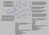
I am attempting to model a version of Hiraga's Le monstre but am having issues with the models for the input JFET's. These are what I am using;
*2SJ74
*Toshiba Dep-Mode 20mA 400mW LowNoise pkg:TO-92B 2,1,3
.MODEL 2SJ74 PJF(Beta=92.12m Rs=7.748 Rd=7.748 Lambda=4.464m
+Vto=-.5428 Cgd=85.67p Pb=.3905 Fc=.5
+Cgs=78.27p Is=12.98p
+Kf=26.64E-18 Af=1)
*2SK170
* 20mA 400mW LowNoise Dep-Mode pkg:TO-92B 3,1,2
.MODEL 2SK170 NJF(Beta=59.86m Rs=4.151 Rd=4.151 Lambda=1.923m
+Vto=-.5024 Cgd=20p Pb=.4746 Fc=.5
+Cgs=25.48p Is=8.477p
+Kf=111.3E-18 Af=1)
However no matter what I set the Source resistor to it will not pass more than 0.4mA. Are these faulty models ?
Shoog
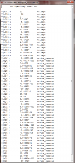
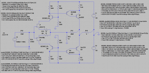
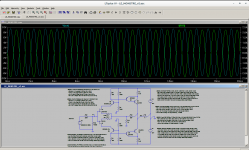
Here is my simulation. I tried a few different models and got the current up to 0.4mA through the input. With this low a current R8 and R7 need to be significantly bigger than the original to get the outputs biased to 700mA.
Shoog
Shoog
Attachments

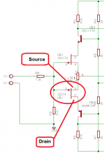
It looks like you have the 2SJ74 "Source" and "Drain" connections reversed. See atch (taken from Amplificateur DIY - Le monstre 8W ).Here is my simulation. . . . .
Values of R7 and R8 may be too large. Try 330 or 470 ohms, sted 3300 ohms.
Dale
Attachments
Last edited:
Ok will try flipping them and see if it solves it. I thoughts that on jfets the Source and drain were interchangable.
Thanks
Shoog
Thanks
Shoog
Last edited:
The atch file works.
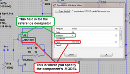
Looking carefully at the screen shot from your original post . . . it looks like you were trying to specify a model ID as the component reference designator. With no .MODEL specified for the transistors, LTSpice defaults to some generic device that sort of behaves like the component in the symbol. See last atch.
Dale
That is supposed to be true for many JFET's, though I haven't done any tests to verify it. It seems to be true for these parts in the atch circuit file.Ok will try flipping them and see if it solves it. I thoughts that on jfets the Source and drain were interchangable.
Looking carefully at the screen shot from your original post . . . it looks like you were trying to specify a model ID as the component reference designator. With no .MODEL specified for the transistors, LTSpice defaults to some generic device that sort of behaves like the component in the symbol. See last atch.
Dale
Attachments

Last edited:
the 2sj74 will have the Drain more negative than the Source.
Try checking the model by simulating ONLY the 2sj74 (and also 2sk170) within a circuit to reproduce the plots shown in the datasheet.
I think this is how some other Members have been developing better models.
Try checking the model by simulating ONLY the 2sj74 (and also 2sk170) within a circuit to reproduce the plots shown in the datasheet.
I think this is how some other Members have been developing better models.
i thought that was only true on some JFETS in "real" circuits (as opposed to simulations).
mlloyd1
mlloyd1
... I thoughts that on jfets the Source and drain were interchangeable ...
The only thing I would like to improve on would be for a better cascode transistor up front, but I am restricted to European ones since I only want to place a single order to RS Components.
Br Cornelius
Br Cornelius
Just wanted to say thanks again Dale.
I was thinking about the driver for the darlington and looking for suitable transistors available within Europe. A trawl through the RS Components cat came up with 2SA1353/2SC3417
2SA1370 ... - Datasheet Search Engine Download
Looks quite nice, does anyone think it would be a step up from the BC550/560 in this position ?
Shoog
much slower and much less gain than a bc550/560
There are many other Sanyo that are much faster, but not much extra gain.
Why go to a To126 medium power transistor? Great for VAS and Pre-driver duty.
There are many other Sanyo that are much faster, but not much extra gain.
Why go to a To126 medium power transistor? Great for VAS and Pre-driver duty.
The curves looked a lot better than the bc550, but it was a none runner since RS doesn't stock its compliment anyway.
I will stick with the BC550/560 for ease of purchase. I hate skooting round obscure suppliers where you have no certainty of what you are getting. I also hate using Mouser due to the postage to Europe. This is predominantly a parts bin build so I don't want to run up a big order for the sake of it.
The peak drive current into the finals is only 33mA for full output (according to spice) so should be well within the 100mA limit of the BC550/560. I might glue the BC550/560 to a piece of aluminium to keep them at the same temperature and offer a bit of cooling.
Shoog
I have seen the PZT3904/PZT3906 (a 2N3904/06 in a medium-power SMD package) suggested for applications like this. Lower current gain than the BC550/560, but that's the price you pay for higher current capability - I think it's rated for 250 mA of collector current. It's quite fast enough, but I don't know if it's readily available in your location.I was thinking about the driver for the darlington and looking for suitable transistors available within Europe . . . .
Dale
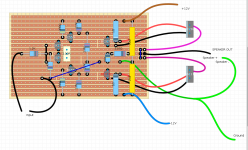
This is what I have finally come up with. I decided that the BC327/337 would be a safer option in the darlington driver. I will be using small heat sinks to keep them nice and cool.
I have reduced the rails to 10V because I want to regulate my supplies and the 12V AC transformer is unlikely to sustain a regulated +/-12V DC.
When I build I will be using massively oversized heatsinks so expect it to run cool at its 940mA bias.
Will upload my perf board layout shortly.
Shoog
I have reduced the rails to 10V because I want to regulate my supplies and the 12V AC transformer is unlikely to sustain a regulated +/-12V DC.
When I build I will be using massively oversized heatsinks so expect it to run cool at its 940mA bias.
Will upload my perf board layout shortly.
Shoog
Attachments
R9 and R10 are enormous value.
Is that why you only get tiny currents?
The value are R10 42R and R9 58R, The asymmetry is there to trim out DC to 2mA at the output.
This is equivalent to a 100R trimmer. Since switching start models the front end is passing about 3mA which is exactly what the original version specifies.
Shoog
I believe the tendency is to run the input buffer at 10mA nowdays. That would require something in the region of 20R.
However, most people are running their versions at standing currents of between 1-2A, which is way more than the original and way more than is necessary to keep it in Class A for 90% of the duty cycle.
Mine will only be running in the 1-3W range for almost all of the time so the 800mA output bias will be more than adequate.
it now models nicely, but the waveform is quite unbalanced at max output suggesting quite high third harmonic when driven hard. Hopefully transistor matching will help.
Shoog
- Status
- Not open for further replies.
- Home
- Amplifiers
- Solid State
- Cannot get 2SK170 2SJ74 Spice model to pass more than 0.4mA