The circuit has not been tested in the exact configuration shown, but it should work. My prototype differs from the schematic in a few ways:
1. Q4, Q5 and R10 are replaced with a single BD680 Darlington transistor
2. Resistor R9 is 22k
3. Q1 has a 22kohm resistor between base and ground
EDIT: 4. Relays are SPDT types (see below)
EDIT: 5. Capacitor C19 is 220uF / 40V
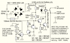
Operation has been tested repeatedly with +30VDC and -30VDC in, with a 4 ohm loudspeaker connected to the circuit. The relays seem to disengage fast enough. This could be speeded up to an extent by adding a zener diode (probably one with less than 30V nominal zener voltage) in series with the 1N4007 diode. The cathode of the zener diode would be connected to the cathode of the 1N4007. The zener diode must have suitable peak power capability.
The relays should have their coils rated for 12 volts nominal. The paralleled resistance of the coils should not be less than 60 ohms. Transistor Q5 should have less than one volt between collector and emitter when the relays are engaged.
Some relays may be too slow to use with this circuit, even with the zener diode added.
The relays used in the prototype are Goodsky GZ-SH-112L. These are single pole double throw (SPDT), 16 ampere units with a 12 volt, 270 ohm coil. The common terminal is connected to the "hot" (not grounded) terminal of the loudspeaker. The normally closed terminal is connected to ground. EDIT: This configuration is recommended (normally closed relay terminals across speaker). SPST relays may not work properly.
The circuit should be first tested with no loudspeaker connected to make sure it responds to both negative and positive DC voltages of approx. 750mV and greater, applied between the "From Amplifier" and "Amplifier Ground" terminals. No DC voltage should be measurable at the output (between terminals "To Speaker" and "Amplifier Ground").
The circuit is not designed to handle input voltages much greater than +30V/-30V or so as the base current of Q1 or Q2 might become excessive. Moreover, many relays are not designed to switch large DC voltages.
The 10VAC input to the circuit should be galvanically isolated from everything in the amplifier that the circuit will be used with. The amplifier should have a dedicated 10VAC winding in its power transformer for this purpose. Optionally, a separate transformer can be used. If the DC resistance of the transformer winding supplying the rectifier bridge is less than 1.5 ohms, a resistor of 1.5 ohms or greater value must be inserted in series with one of the leads of the winding to limit the peak current through the rectifier diodes when the 2200uF capacitor charges up. The minimum allowed series resistance will depend on the exact rectifier diodes used. For the SKB 2/02 L5A bridge rectifier this is actually 1 ohm.
Powering the circuit with AC has not been tested (tested only with batteries or with unfiltered DC). This should not make a difference in operation.
Any potential improvements to the circuit would be appreciated.
E.H.
EDIT: R42 must be rated at least 500mW. Two 22kohm, 500mW resistors connected in parallel can be used to replace R42 for reliability. The prototype has a 10kohm, 1 watt metal film resistor for R42.
1. Q4, Q5 and R10 are replaced with a single BD680 Darlington transistor
2. Resistor R9 is 22k
3. Q1 has a 22kohm resistor between base and ground
EDIT: 4. Relays are SPDT types (see below)
EDIT: 5. Capacitor C19 is 220uF / 40V
Operation has been tested repeatedly with +30VDC and -30VDC in, with a 4 ohm loudspeaker connected to the circuit. The relays seem to disengage fast enough. This could be speeded up to an extent by adding a zener diode (probably one with less than 30V nominal zener voltage) in series with the 1N4007 diode. The cathode of the zener diode would be connected to the cathode of the 1N4007. The zener diode must have suitable peak power capability.
The relays should have their coils rated for 12 volts nominal. The paralleled resistance of the coils should not be less than 60 ohms. Transistor Q5 should have less than one volt between collector and emitter when the relays are engaged.
Some relays may be too slow to use with this circuit, even with the zener diode added.
The relays used in the prototype are Goodsky GZ-SH-112L. These are single pole double throw (SPDT), 16 ampere units with a 12 volt, 270 ohm coil. The common terminal is connected to the "hot" (not grounded) terminal of the loudspeaker. The normally closed terminal is connected to ground. EDIT: This configuration is recommended (normally closed relay terminals across speaker). SPST relays may not work properly.
The circuit should be first tested with no loudspeaker connected to make sure it responds to both negative and positive DC voltages of approx. 750mV and greater, applied between the "From Amplifier" and "Amplifier Ground" terminals. No DC voltage should be measurable at the output (between terminals "To Speaker" and "Amplifier Ground").
The circuit is not designed to handle input voltages much greater than +30V/-30V or so as the base current of Q1 or Q2 might become excessive. Moreover, many relays are not designed to switch large DC voltages.
The 10VAC input to the circuit should be galvanically isolated from everything in the amplifier that the circuit will be used with. The amplifier should have a dedicated 10VAC winding in its power transformer for this purpose. Optionally, a separate transformer can be used. If the DC resistance of the transformer winding supplying the rectifier bridge is less than 1.5 ohms, a resistor of 1.5 ohms or greater value must be inserted in series with one of the leads of the winding to limit the peak current through the rectifier diodes when the 2200uF capacitor charges up. The minimum allowed series resistance will depend on the exact rectifier diodes used. For the SKB 2/02 L5A bridge rectifier this is actually 1 ohm.
Powering the circuit with AC has not been tested (tested only with batteries or with unfiltered DC). This should not make a difference in operation.
Any potential improvements to the circuit would be appreciated.
E.H.
EDIT: R42 must be rated at least 500mW. Two 22kohm, 500mW resistors connected in parallel can be used to replace R42 for reliability. The prototype has a 10kohm, 1 watt metal film resistor for R42.
Attachments
Last edited:
How old is this circuit.
It's been a while since I've seen a positive ground.
I love looking at old circuits and was always amazed by all the pnp transistors and positive grounds.
When I was at college it was mostly npns in the circuits.
Regards
I have some PNP germanium transistors laying around and intended to experiment with using them for Q1 and Q2. That's why a positive ground was used. The germanium devices should lower the DC voltage detection thresholds but some of them may have excessive leakage currents to be used here.
The prototype has been modified by removing the 22kohm resistor not mentioned on the schematic. Also, R9 is now 47k as per the schematic. I also added a 333 1/3 ohm resistance (three 1kohm, 1 watt resistors connected in parallel) in series with the 1N4007 diode (the diode may be a different one; the type number is not completely visible as the diode is mounted on a circuit board). The 1kohm resistors seem to make the relay disengage slightly faster. A zener diode should be even better in this regard.
There seems to be a problem with response time when a positive voltage is presented at the input terminals (48V tested). Does anyone have any idea as to what might be causing this? I suspect that Q4's base voltage must be pulled rather close to ground potential in order to get the fastest response. At present, the base-emitter voltage drop of Q3 causes Q4's base voltage to be approx. 600mV higher than what it will be when Q1 turns hard on, as is the case with large negative input voltages.
(In the above paragraph, Q4 refers to the internal driver transistor in the BD680. If you used a Darlington pair composed of discrete transistors, the base voltage problem with Q4 would likely be identical.)
It might be worth experimenting to add one more BC327 PNP transistor to the circuit. The base of the transistor would be connected to ground. The emitter would be connected to terminal "From Amplifier" via a 10kohm resistor, and the collector would connect to Q4's base. Two 2.2uF aluminum electrolytic capacitors connected in series, with their positive terminals connected together, would then be added between ground and the emitter of the new transistor. A 1N4007 silicon diode with its anode grounded and its cathode connected to the emitter of the added transistor would be required, as well.
This just might do the trick.
Another thing to try would be to short out the 47k resistor.
Any suggestions would be gratefully received. I would be interested to know just how fast a loudspeaker protection circuit like this needs to be in order to do its job properly.
Regards,
E.H.
Last edited:
the darlington connected transistor driving the relay coil would be far better replaced with a pair of transistors. one driving the relay coil in saturated mode and then the second driving the base of that main driver with just enough current to saturate it.
That will reduce the Vdrop from ~800mV to ~100mV.
You gain 0.7V across the relay at the cost of one extra 1/4W resistor.
That will reduce the Vdrop from ~800mV to ~100mV.
You gain 0.7V across the relay at the cost of one extra 1/4W resistor.
Thanks. This may be a good thing to do especially if the power supply voltage is on the low side. There should be approx. 12 volts on the 2200uF capacitor. The AC input to the circuit may need to be somewhat higher than 10 volts to achieve this. I was very surprised to find that the 100mA slow blow fuse drops approximately one volt when the relays are energized and when a 14.8 volt battery is used to power the circuit.
Quote:
At present, the base-emitter voltage drop of Q3 causes Q4's base voltage to be approx. 600mV higher than what it will be when Q1 turns hard on (...).
This seems to be wrong. I measured less than 30mV between Q4's base and ground after a DC voltage of 2 volts was applied to the circuit, regardless of the polarity of this voltage. There still seems to be a small difference in response times depending on the DC voltage polarity. This may not be very important.
Quote:
(...) make the relay disengage slightly faster.
Should be "relays".
Quote:
At present, the base-emitter voltage drop of Q3 causes Q4's base voltage to be approx. 600mV higher than what it will be when Q1 turns hard on (...).
This seems to be wrong. I measured less than 30mV between Q4's base and ground after a DC voltage of 2 volts was applied to the circuit, regardless of the polarity of this voltage. There still seems to be a small difference in response times depending on the DC voltage polarity. This may not be very important.
Quote:
(...) make the relay disengage slightly faster.
Should be "relays".
- Status
- This old topic is closed. If you want to reopen this topic, contact a moderator using the "Report Post" button.