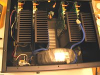
I have Sonance 5150 (5 x 150W) made by ATI with a bad channel. I don't think I will ever find a schematic, but for someone who knows what there doing (omits me) it seems like a pretty straight forward design. Built like a monoblock but with one big transformer. One channel had one of it's fuses blown (two fuses per channel). I replaced the fuse and it opened right away on power up and I measured 6V DC at outputs.
The output transistors on one side where shorted. There are three per side. I replaced all six output transistors (3 PNP,3 NPN) and the two drivers? Powered it up for a brief instant - magic smoke, fuse opened, and some shorted transistors.
Transformer is putting in 56V AC x 2 into the board (same for all cards). 70V DC out of both rectifiers. The emitter resistors all mesaure .5 ohms. I temporarily put in 1 output transistor on each side and backed the bias all the way off. No smoke or blown fuse, transistors not shorted, but 9V DC at the outputs.
Nothing seems visibly fried except for a very small burn mark between two of the legs of the driver transistor on the side with blown fuse. Clearly there is something else amiss. I am trying not to do further damage. My experience and knowledge are limited so at this point I am shooting in the dark.
Any ideas or things I might check to help narrow down what the problem may be would be appreciated. I have included a couple of pics. I can pull another card for comparison but I am not sure where to be looking.
Attachments
Why is one output in backwards?
Why haven't you removed the carbon track (by scraping) and sealed the board with epoxy?
Why didn't you replace the drivers?
The output is in correctly, just at an angle downwards, the pic made it look dark (shadowed). I lightly tacked in 2 outputs just to get some power on readings. Didn't want to smoke all 6 outputs. That side came loose when I unmounted from the sink to take the pics.
I did replace the drivers along with the all of the outputs at the same time. I did not replace the one transistor in the very center, the one that does not have a screw mount. Not sure what that one is..
Unsure about the carbon track you are referring to? The black dot by the driver is the size of a pinpoint and I did clean that. Digging into the board any further seemed counter productive. There is no conductivity between the pads there.
Build and use a Mains bulb tester.
56-0-56Vac giving +-70Vdc does not equate to 150W into 8r0 amplifiers.
Can you elaborate on what wattage those voltage readings should equate to, or conversely what voltages you would expect to see for a 150W amp?
I checked a functional channel and those readings are similar. All other channels have less then 10mV DC at the outputs and seem to be working properly. Very quiet, no hum or noise, clear sound output. I have not put it on a scope and driven it hard into a load bank, but audibly playing music at normal levels it sounds just fine.
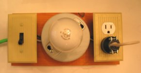
I do have (built it some years ago) a mains bulb tester. I have included a pic. It does work properly - when switched on with the shorting plug in, the light illuminates and draws 100W. With the shorting plug removed and soldering iron, fan etc.. are plugged in no light and device works and draws the proper amount of current.
However, even with the bad channel disconnected, when put in line with the amp there is an issue. It creates a relay chatter in the amp (relay rapidly opening and closing) causing the light to flash. I do not know why, I assume it has something to do with the protection circuit in the amp. I would need a better understanding of what is occurring before putting it inline again. But I do not believe this is an issue with the amp, rather an interaction issue with the main bulb tester that I do not understand. Thoughts on this?
Without the mains bulb tester inline, the amp powers up and relays open without issue. After inrush, idle current draw with 4 good channels, or all five channels for that matter, is in the 70-80W range. This I assume is about right, if anything a bit low. Bias is about 6mV in all channels across an emitter resistor.
I do also have a variac. But I have always been concerned with, and would love more insight into, pushing less power into the device then it was designed to use. Example, if using the variac at low voltage would the amps relays even open? Would it not appear to the device like a real nasty brown out? Again without a better grasp on the underlying mechanics, I do not use.
I am thinking that when the outputs shorted, some other component(s) also gave up the ghost. But again, I am green, and don't really know where to focus my attention. I am looking for insight into what likely could also have been damaged during the short, beyond the 6 main outputs and 2 drivers.
Attachments
muddler, remove faulty channel and carry out voltage checks on the working channels that way you can use this to solve the faulty one... Also your amplifier can work on a lower rail supply so you don't damage any more part's... also before refitting more parts in check the bias voltage on the working modules that way your know what to set the amp up as...mv across emitter resistors way or current method over the positive supply feed..
Dc voltage on the o/p of 5v would lead back to the vas and i/p tail pairs, check your small transistors/and resistors for o/c.
As Andrew T says 70v per rail is more than 150w per channel..
Dc voltage on the o/p of 5v would lead back to the vas and i/p tail pairs, check your small transistors/and resistors for o/c.
As Andrew T says 70v per rail is more than 150w per channel..
trouble shooting..
If you pull the o/ps and left one pair in to power up is not good on 70v rail's..
Here's a quick guide.. volt check supply rails at each side of the filter caps and follow the supply to each collector leg of the o/p's middle.. your base if ok will be low volt and a few mv on the emitter leg.. you can drain the the main caps via 4k7 3w resistors to ensure you don't get zapped..
If you want to, remove the fuses to the faulty board and solder 100 ohm 2w resistors in each fuse holder to that board these will act as current limiters so no parts get fried.. these will get hot if s/c and stay cold when no s/c...
leave off loading the amplifier till the fault has been cleared...
I have Sonance 5150 (5 x 150W) made by ATI with a bad channel. I don't think I will ever find a schematic, but for someone who knows what there doing (omits me) it seems like a pretty straight forward design. Built like a monoblock but with one big transformer. One channel had one of it's fuses blown (two fuses per channel). I replaced the fuse and it opened right away on power up and I measured 6V DC at outputs.
The output transistors on one side where shorted. There are three per side. I replaced all six output transistors (3 PNP,3 NPN) and the two drivers? Powered it up for a brief instant - magic smoke, fuse opened, and some shorted transistors.
Transformer is putting in 56V AC x 2 into the board (same for all cards). 70V DC out of both rectifiers. The emitter resistors all mesaure .5 ohms. I temporarily put in 1 output transistor on each side and backed the bias all the way off. No smoke or blown fuse, transistors not shorted, but 9V DC at the outputs.
Nothing seems visibly fried except for a very small burn mark between two of the legs of the driver transistor on the side with blown fuse. Clearly there is something else amiss. I am trying not to do further damage. My experience and knowledge are limited so at this point I am shooting in the dark.
Any ideas or things I might check to help narrow down what the problem may be would be appreciated. I have included a couple of pics. I can pull another card for comparison but I am not sure where to be looking.
If you pull the o/ps and left one pair in to power up is not good on 70v rail's..
Here's a quick guide.. volt check supply rails at each side of the filter caps and follow the supply to each collector leg of the o/p's middle.. your base if ok will be low volt and a few mv on the emitter leg.. you can drain the the main caps via 4k7 3w resistors to ensure you don't get zapped..
If you want to, remove the fuses to the faulty board and solder 100 ohm 2w resistors in each fuse holder to that board these will act as current limiters so no parts get fried.. these will get hot if s/c and stay cold when no s/c...
leave off loading the amplifier till the fault has been cleared...
Amptech - Thanks for the advice, I appreciate you helping me work this out. I did as you suggested. Started by making a quick capacitor drain with a spare big resistor, wire, clips, and some shrink tubing. I can put my meter probes into the clips and watch the cap drain down.
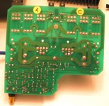
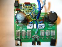
I traced the issue to a 10 Ohm resistor that was measuring in the mega ohms. If you look at the pic with the components facing up, just to the bottom left of the large cap on the left, half covered by the cap in the picture, running parallel to the fuse, is the resistor. One leg of the resistor goes to the side of fuse that is tied to the o/ps collector, the other leg goes off towards the input. Not sure what it does... guesses ?
DC offset went from 9 volts to 8mV (all channels are now between 6-8mV). Put in fresh o/ps. Let it idle for 30 min. Set bias to 5mV (what the other channels were at), rechecked after another 30 min. Draw is about 90W at idle and the hottest part of each of the sinks measures at 113F (45C). I am assuming this is all normal.
I think the rail voltage is also where it is supposed to be. I remeasured all channels and I am getting rails of 68V on all. The published specs are:
All channels driven
Power Output: 165 W/ch x 5 @ 8 Ohms / 200 W/ch x 5 @ 4 Ohms
Dynamic Headroom: +2.5 dB x 5 @ 8 Ohms / +1 dB x 5 @ 4 Ohms
Total Harmonic Distortion: 0.03% 20Hz-20kHz @ 8 Ohms / 0.10% 20Hz-20kHz @ 4 Ohms.
Power Consumption: 1800 Watts maximum 4 Ohms, full power. BTU/HR: 2732
AC Fuse: 15A, 250V, 314 Type/MDL
Weight: 83 lbs. (38 kg)
I imagine driving 2 channels output is a touch higher also, would this not equate to 68V rails? Regardless, it is dead quiet with the volume down and sounds wonderful when playing music.
Is that 10r between Signal Ground and Power Ground?
If so then during a fault condition it may try to pass enormous current compared to the pA, or uA, that usually passes.
The Signal Ground to Power Ground resistor must be bypassed with a pair of inverse parallel diodes that can pass a fault current.
If so then during a fault condition it may try to pass enormous current compared to the pA, or uA, that usually passes.
The Signal Ground to Power Ground resistor must be bypassed with a pair of inverse parallel diodes that can pass a fault current.
Is that 10r between Signal Ground and Power Ground?
I really don't know. If I recall, the other leg went to a 100uf cap.
- Status
- This old topic is closed. If you want to reopen this topic, contact a moderator using the "Report Post" button.
- Home
- Amplifiers
- Solid State
- Amplifier Troubleshooting Need Help