Here below the main reason which move me to start a new topic:

This schematic has originated by an inquiry of mine about a possible path to improve the design of famous JLH amplifier, published in 1969 on Wireless World by John Linsley Hood and since then reproduced by innumerable diyers ubiquitously in the world.
The main bigger problems of this old amplifier are 1) a poorly defined quiescent current, too dependent ffrom hfe parameter of output transistor, which may lead the amplififier in an unsafe operating mode or in a plain, disastrous thermal runaway and 2) a very limited open loop gain (about 400 or 52 dB) that result in a minimal SVRR, in effect so feeble that a stabilized, full effectiverly filtered power supply became mandatory.
The root of first problem is physical and cannot be without the adoption of adeguate thermal monitoring system which exert an effective control of queiscent current of the output stages, surely more effective than of the original design which, in fact, is "limited" just by the ohmic resistance of the wiring from internal emitter pad of the die ad the external pin of the case - a resistance of value comprised between 100 and 200 milliohm.
The second problem instead has is roots in a VAS stage "a bit" overwhelmed and working on a too low loading impedance (dinamically just a bit below one kohm)
Before of trying to solve these probve I've had to devise something of the effective working principle of the output stage, wich in spite of its flaws, is very interesting by itserf but too long to be explained here: in synthesis, while the upper output transistro work just as the plain emitter-follower that is, the lower stage act as an active partially NEGATIVE load which lead the effective load of the amplifier to appear as if would have an HIGHER value than effectively has. This "increased value" load (that effectively appear to the upper section of output stage multiplied by about seven times) is also the main responsibile of the big part of VAS amplifier gain, that otherwise would fall to about 50-55 times of open loop gain - not exactly a bucolic one...
After some reasoning i've arrived to the schematic depicted in figure which, in order to solve the problen of the original Linsley Hood output stage, has been effectively splitted in TWO amplifiers working on the same load: a fiist VOLTAGE amplifier, which is essentially a classic, high gain VAS (here represented by the voltage generator V2) and a "servo CURRENT amplifier" which, while sensing the current flowing on R1 of 0.22 ohm, really supply the required current to the load when the VAS, trough the emitter follower that buffer it, impose on the load itself a voltage as required by the audio signal driving the system.
In synthesis: the upper stage supply to the load the amplified audio VOLTAGE, while the lower stage act as an ancillary CURRENT amplifier which provides the current required by the load to sustain the voltage imposed on it.
The direct conseguence of this situation on the upper voltage stage (the emitter follower) is that it work really on a constant current basis, effectively minimizing the big part of his contribute to the overall distortion. A more subtle consequence is however the fact that the current amplifier acts as a sort of "Power Factor Controller" which strongly reduces the reactivity of the load, improving the stability of the voltage amplifier section once the general negative VOLTAGE feeedback is applied to the amplifier (in the usual classical way).
About the stability of the CURRENT pover amplifier (the lower section), although it cannot be totally seamless, the worries can be strongly reduced considering that:
1) This amplifier DON'T need an huge open loop gain because it don't need to supply the TOTAL current required by the load but just a reasonable quantity enough to obtain a a good reduction of the variation of current which fflow on R1 and hence in the upper emitter follower section (which however continue to work on a more tlither load than the real connected at the output).
2) This amplifier neither need a full operating bandwidth, which can be effectively limited to about 10 kHz without any serious messing up of the performance of the system in the upper part of the audio bandwidth (about 10-20 kHz), which energy content can be quietly treated by a simple emitter follower loaded by a fixed current generator - the effective circuit which reduces the system once the current amplifier run out of its power bandwidth.
This concept is here applied to a class A amplifier because the original goal was just the updating of the JLH class A amplifier. Nothing however is of obstacle to the extension of the concept at a normal class AB amplifier where, while an adequately beefed-up VAS can drive "directly" the load as a (relatively) low power class A voltage amplifier, the normal class AB output stage, adequately backed by a servo amplifier, can act as a power CURRENT DUMPER in a manner very similar to that is operating in che QUAD 405 and successively derived amplifiers.
That's all for now. I wait your observvation but, first of all, your critic on the concept - not on the economy of design, please: I know yet that is a "non-economy-amplifier" very poorly competitive wih a well designed class AB amplifier but at the moment I don't pay any care for this worries! 🙂
Ciao
Piercarlo
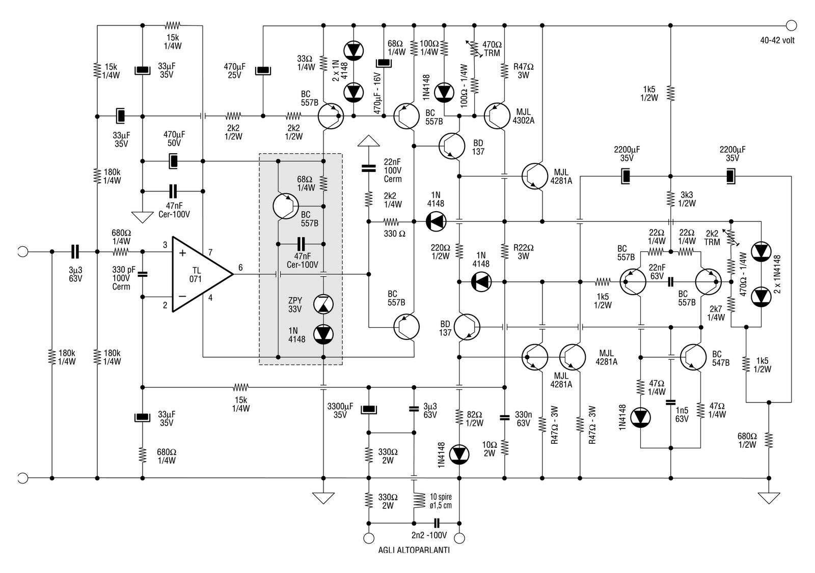
Here the schematic of a prototype Class A Amplifier based on the design idea proposed. PCB layout is in the defining stage. The whole VAS stage (and also input stage) is worked out around a TL 071 for sake of stability.
I always wait for your comments! I do not eat anyone! 🙂
Piercarlo
I always wait for your comments! I do not eat anyone! 🙂
Piercarlo
Hi,
I cant even tell where you supposed to connect the speaker.
A JLH with a current dumper is an idea, I can't see it here.
rgds, sreten.
Feedforward current dumping is a low power high quality
amplifier arranged to not only amplify but to also cancel
the errors of a brute force "current amplifier", leaving
you with the small amplifier high quality sound and
whatever it cannot cancel from the brute force amp.
Last edited:
Hi,
I cant even tell where you supposed to connect the speaker
Pin out named "AGLI ALTOPARLANTI" (Loudspeakers in italian)
A JLH with a current dumper is an idea, I can't see it here.
JLH has just INSPIRED this amplifier (after an in-depth inquiry about its real working modes). This is an amplifier by its own, not a clone of the JLH (even it's named "JLH-2012")
Feedforward current dumping is a low power high quality
amplifier arranged to not only amplify but to also cancel
the errors of a brute force "current amplifier", leaving
you with the small amplifier high quality sound and
whatever it cannot cancel from the brute force amp
This amplifier has NOTHING to do with feedforward amp of QUAD or similiars. Feedforward and Current Dump are just TWO distinct concept. Here I've took in design just one (the last). However even the Quad amplifier is not a "pure" feedforward but instead a feedforward system embedded inside a normal NFB system.
Regards
Piercarlo
- Status
- Not open for further replies.