Hi, I have one of these speaker protection boards from eBay.
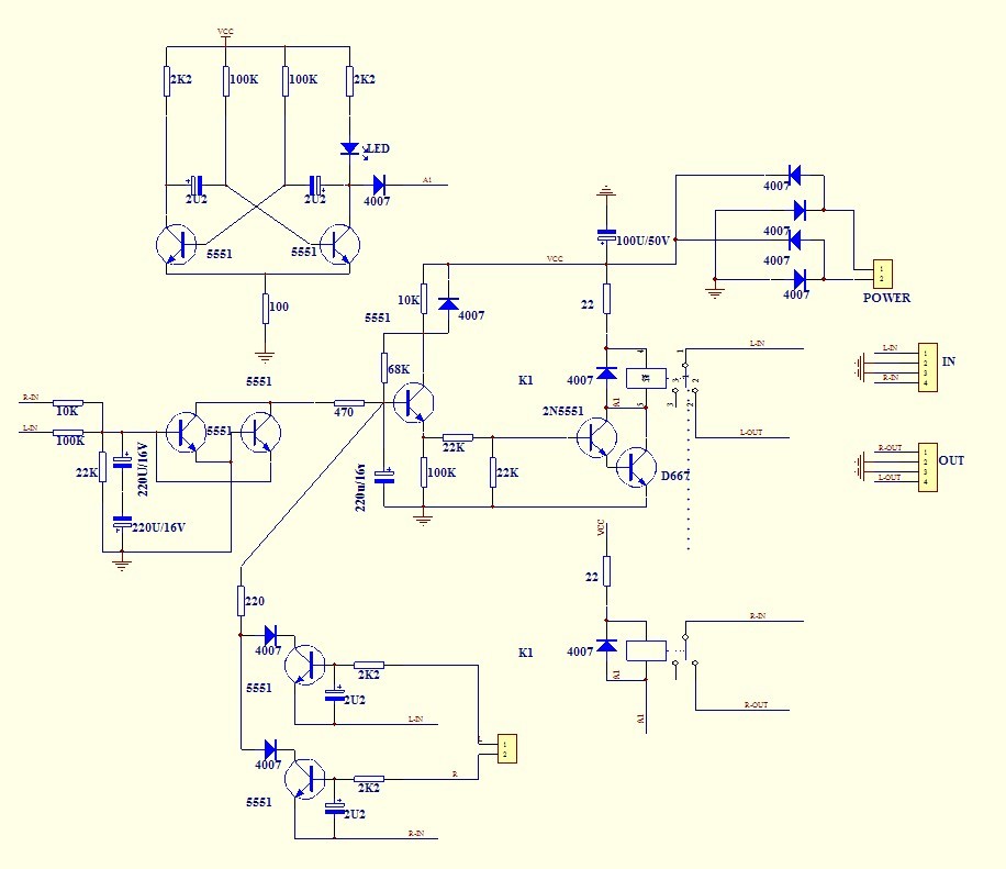
I can see a few issues on the diagram maybe. 1st on the left of the diagram R-In is via 10K and L-In is via 100K. I would guess one of these is wrong!! It looks like the resistor is a potential divider with the 22k to GND.
Next mistake is on the PSU. There is no 7812 reg in the PSU which there is on the board.!!!!
Finally and most important maybe?? At the bottom of the diagram, there is an input L and R which looks like it should be different from L-In and R-In. What are these inputs for?? Line level on the preamp maybe??? not really sure!
Any help would be greatly appreciated!
Thanks Ian

30A speaker protection board kit WLX-7 | eBay
I can see a few issues on the diagram maybe. 1st on the left of the diagram R-In is via 10K and L-In is via 100K. I would guess one of these is wrong!! It looks like the resistor is a potential divider with the 22k to GND.
Next mistake is on the PSU. There is no 7812 reg in the PSU which there is on the board.!!!!
Finally and most important maybe?? At the bottom of the diagram, there is an input L and R which looks like it should be different from L-In and R-In. What are these inputs for?? Line level on the preamp maybe??? not really sure!
Any help would be greatly appreciated!
Thanks Ian
30A speaker protection board kit WLX-7 | eBay
The relay is depicted on the r/h side and the R-IN and R-OUT refer to the speaker leads IN from the amplifier and OUT to the output terminals. That is how the device protects and mutes the speakers, by switching them in or out of circuit. A dotted line shows tandem operation of the identical Left channel above. The yellow blocks on the extreme right are just detail of the connector blocks. 'Poor drawing practice, but logic wins eventually.
Dodgy circuit diagrams posted on the Ebay sites are normal to avoid copying which is the main industry there. Check the actual board to find whether the resistance fitted is either value, but it probably only shows the range possible, which is seldom critical anyway.
A 7812 regulator is not shown in the pic. either, so contact the supplier for a current circuit diagram, or just supply it with 12-18V AC, or omit it and simply use an unregulated 9V AC supply. It's not very critical circuitry, after all.
Thanks ;-)
I'm not so fussed about the regulator bit as its straight forward and the other couple of errors were pointed out as I knew someone else would")
What I'm most interested in is the sense part of the circuit. I can see that there are various points that connect to L&R in but there is also part of the circuit towards the lower of the diagram that I don't understand. There is an additional input marked as L & R. Any idea what these are for? Thanks
I'm not so fussed about the regulator bit as its straight forward and the other couple of errors were pointed out as I knew someone else would
What I'm most interested in is the sense part of the circuit. I can see that there are various points that connect to L&R in but there is also part of the circuit towards the lower of the diagram that I don't understand. There is an additional input marked as L & R. Any idea what these are for? Thanks
Nearly 2 years ago, a thread titled "Jim's Audio 30A speaker relay" (or close) looked at the same questions for an identical product. The unidentified terminals were attached, it was found by contacting Jim's Audio, to the emitter of a power transistor in the -ve side of an EF power amplifier output stage. IOW, those connections monitored output stage current by sampling voltage across an emitter resistor, both channels, in a particular design amplifier - probably a PA size amp as the 30Amp capacity suggests.
You could adapt by trial and error to smaller amplifiers with large enough emitter resistors but I haven't considered it. It's superfluous in Hifi and won't react fast enough to cut the load in a lot of overload situations. The polarity would follow that of the electrolytics, meaning that leads from either terminal block connection go to both emitters but the other leads go, in common with similar marked leads, to the outputs. These common connections, are prewired on the PCB and you only need to be concerned about the terminal block connections, if you look at it. 'Another case of poor drawing practice. Ignore the feature.
Recapping, those 10 and 100k resistors don't connect externally - they are part of the on board circuit. The legend of the leads in red only labels what they connect to in the rest of the circuit.
- Status
- This old topic is closed. If you want to reopen this topic, contact a moderator using the "Report Post" button.